~ 4 ~
R u b b e r
Bum p e r s
COOL
END
WARM
END
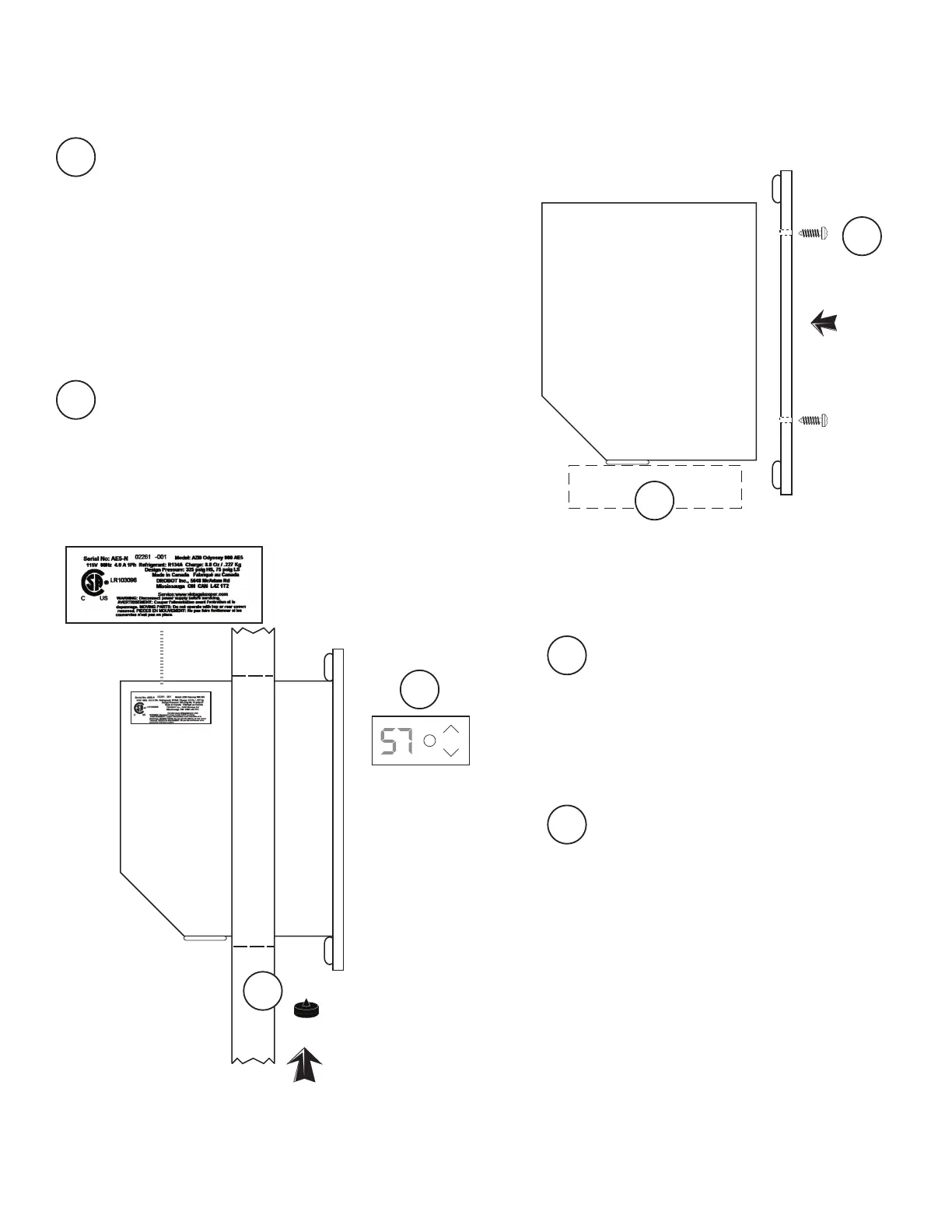
Faceplate
SET
ADJUST
1 OUT 2
Drobot Controls
TM
SERIAL NUMBER
Lift unit carefully and place it on a table
top edge or a thick book.
NOTE :
Fasten the faceplate to the WARM END
with 4 small screws provided.
For model SLIMLINE, faceplate has a
protective coating, which may be peeled
off prior to installation.
1
The end with Control Panel,
power cord and digital sensor is
the COOL END and will extend
INSIDE the enclosure.
The opposite end is the WARM
END, and will mount ush to
OUTSIDE surface of wall.
2
Plug the unit in and test the cooling and
controller functions (see page for opera-
tion instructions).
NOTE:
Lift unit up into cutout opening. With
the assistance of a helper, lift from both
WARM and COOL ENDS to move unit
partly into position.
Install three large rubber bumpers in
holes* on underside of unit near the
WARM END. (Some force may be required;
bumpers are more easily installed with a
twisting motion).
* For Model SLIMLINE, two sets of holes
are provided. If installing through a door,
use the set of holes closest to faceplate.
For installation in other locations (i.e.,
through a wall), use the holes nearer
the middle of the unit.
Copy the serial number to your
warranty registration form. Unit
has a 1-minute delay between
plug-in and start-up .
3
4
1
2
4
3
HOW TO INSTALL YOUR COOLING UNIT