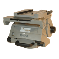
Vector 750i encoded pantographic manual head
24
Set the tilt brake lever [4] from the OFF to the ON position.
If brake pressure is not felt after approximately one-third of lever travel, turn the grub
screw [4.1] clockwise until this is achieved.
Set the tilt brake lever [4] to the OFF position and ensure that the platform is free to
move.
The pan brake is adjusted by turning the pin [3.3]. To gain access to the pin it is necessary to
remove the payload from the head, remove the head from its mounting and remove the
coverplate of the battery housing from the underside of the head.
To adjust the pan brake (see (Fig. 11) above), proceed as follows:
Remove the payload from the head.
Remove the head from its mounting.
On the underside of the head, remove three screws [3.2] securing the coverplate [3.1].
Set the pan brake lever [3] from the OFF to the ON position.
If brake pressure is not felt after approximately one-third of lever travel, turn the pin [3.3]
clockwise until this is achieved.
Set the pan brake lever [3] to the OFF position and ensure that the head is free to rotate.
Refit the coverplate [3.1] and secure with three screws [3.2].
Balance and slide plate calibration
The full scale of both the balance sensor and the slide plate sensor will need calibrating, either
in the factory or in the field, for instance after a battery change. Proceed as follows:
To enter calibration mode, press and hold the level bubble illumination button [7] (see
(Fig. 1) on page 9) and the numeric display button [2] simultaneously for 2 seconds.
The display will change to show ‘CAL’, flashing slowly.
Once in calibration mode, move the slide plate to its mechanical extremes in both
directions (values range from 0–300 mm) and wind the Perfect Balance adjustment
knob [21] to its mechanical extremes in both directions. The controller monitors the
measurements and stores the maximum and minimum values.
To complete calibration, press and hold the display button [2] for 2 seconds. The
software then stores the calibration limits in flash memory and flashes ‘CAL’ five times
rapidly.
Warning!
Remove the payload before adjusting the pan brake.
NOTE: Calibration limits for a given sensor are only stored if sufficient movement has
been detected on that sensor. This allows one sensor to be calibrated at a time.
If no movement has been detected on either sensor within 15 seconds, the
calibration mode is aborted and no calibration limits are stored.