17
Contents
Previous
Page
First
Page
Next
Page
Previous
View
engaged and then, mount and secure the camera/lens combination, with their combined centre of gravity
approximately over the head tilt axis.
Wedge adaptor fixing
10 The adaptor (if not already fitted) is attached to the platform slide plate by either two 3/8 in. BSW
screws passed through the slide plate slots into threaded inserts in the adaptor body, or by a minimum of four
M4 screws passed through the adaptor body into the appropriate threaded holes in the slide plate. The wedge
assembly is secured to the camera underside by one or two captive screws in the wedge assembly.
11 Recheck that the head CENTRE LOCK is engaged on the platform and pull out the wedge adaptor lock
bar until it is held by the action of the lock pin. Offer the wedge assembly into the forward end of the adaptor
body pushing the lock slide assembly against the spring tension. Lower the rear end of the wedge assembly
into the adaptor body and the wedge slide will secure the rear of the wedge assembly. An audible click
indicates correct engagement.
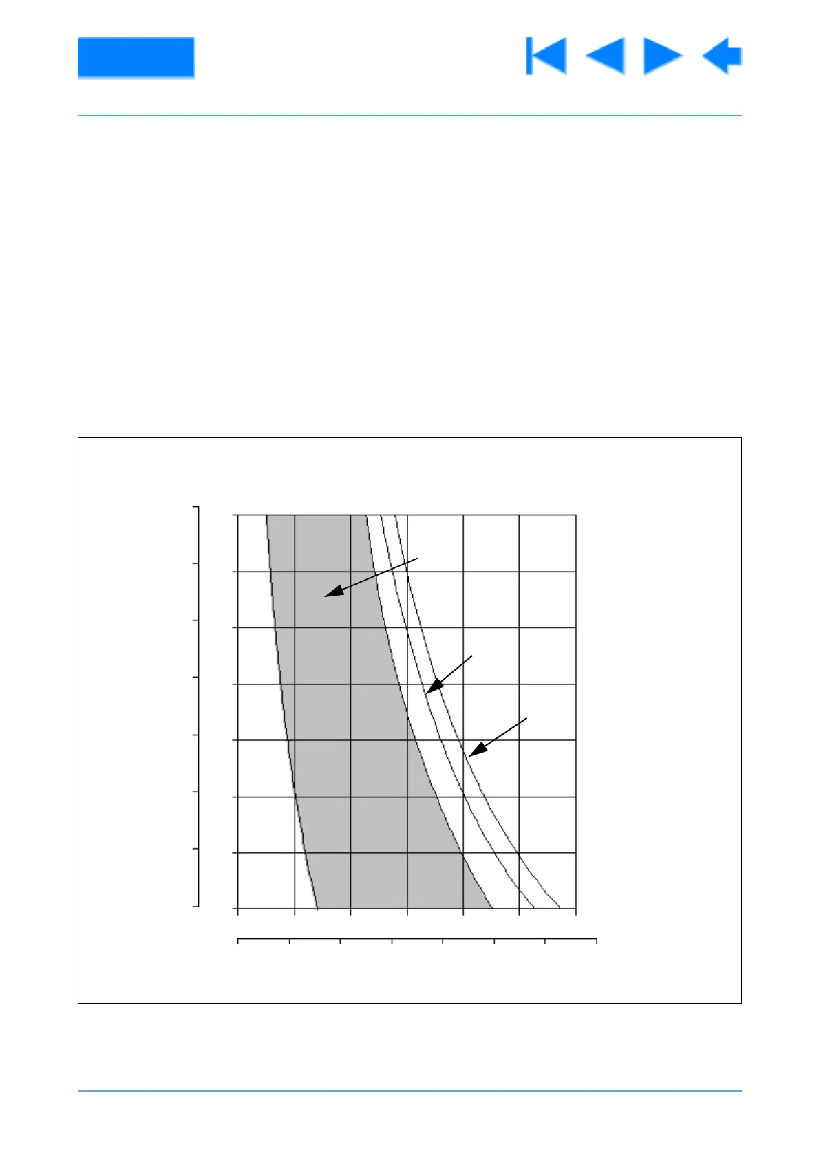
Fig 2.1 Balance Graph
75
100
125
175
200
225
01020304050 kg
150
250
60
0 20 40 60 80 100 120 lb
3
4
5
6
7
8
9
10
mmin.
140
± 90°
± 40°
± 60°
 Loading...


