15
Contents
Previous
Page
First
Page
Next
Page
Previous
View
Section 2
Operation
Contents Para
General. . . . . . . . . . . . . . . . . . . . . . . . . . . . . . . . . . . . . . . . . . . . . . . . . . . . . . . . . . . . . . . . . . . . . . . . . . . . . . . 1
Installation
Fitting the head to its support mounting. . . . . . . . . . . . . . . . . . . . . . . . . . . . . . . . . . . . . . . . . . . . . . . . . . . 3
Pan bar attachment . . . . . . . . . . . . . . . . . . . . . . . . . . . . . . . . . . . . . . . . . . . . . . . . . . . . . . . . . . . . . . . . . . 6
Fitting a camera to the head . . . . . . . . . . . . . . . . . . . . . . . . . . . . . . . . . . . . . . . . . . . . . . . . . . . . . . . . . . . 8
Centre screw fixing . . . . . . . . . . . . . . . . . . . . . . . . . . . . . . . . . . . . . . . . . . . . . . . . . . . . . . . . . . . . . . . . 9
Wedge adaptor fixing . . . . . . . . . . . . . . . . . . . . . . . . . . . . . . . . . . . . . . . . . . . . . . . . . . . . . . . . . . . . . 10
Balancing the camera . . . . . . . . . . . . . . . . . . . . . . . . . . . . . . . . . . . . . . . . . . . . . . . . . . . . . . . . . . . . . . . 12
Setting the tilt drag. . . . . . . . . . . . . . . . . . . . . . . . . . . . . . . . . . . . . . . . . . . . . . . . . . . . . . . . . . . . . . . . . . 15
Setting the pan drag. . . . . . . . . . . . . . . . . . . . . . . . . . . . . . . . . . . . . . . . . . . . . . . . . . . . . . . . . . . . . . . . . 16
Setting the pan and tilt brakes . . . . . . . . . . . . . . . . . . . . . . . . . . . . . . . . . . . . . . . . . . . . . . . . . . . . . . . . . 17
Operation. . . . . . . . . . . . . . . . . . . . . . . . . . . . . . . . . . . . . . . . . . . . . . . . . . . . . . . . . . . . . . . . . . . . . . . . . . . . 18
General
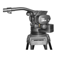
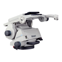
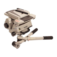
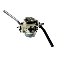
1 The Vision 30 Head is part of a range including the Vision 5, 10 and 20 heads. It may be supplied
already fitted in a carrying case within a packing case.
2 After removal of the head from its packing ensure that the TILT BRAKE and PAN BRAKE levers are set
to the ’ON’ position (levers fully clockwise) with the camera mounting platform parallel with the base and the
CENTRE LOCK engaged (control knob almost touching side wall of platform). he CENTRE LOCK is provided
to retain the platform in a rigid position for fitting and/or removing camera and/or lenses and for safety when a
mounted camera is left unattended. The pin of the lock is biased to engage under spring pressure.
WARNING!: Do not rely on the tilt brake mechanism alone during camera mounting/dis-
mounting - use the centre lock.





 To Next Page