Do you have a question about the Viper 500 ESP and is the answer not in the manual?
Instructions on locating and connecting a constant 12V power source, including fusing.
Guidance on identifying the 12V switched ignition wire for system power.
Steps to locate the vehicle's starter wire using a multimeter for proper connection.
Details the function and application of the H1/1 Orange wire, including its role in starter kill relay.
Details connecting the H1/9 Yellow wire to the ignition for system power and starter kill.
Instructions for connecting the H1/11 Red wire to a constant 12V power source.
Guide for connecting the H2 harness to various door lock system types.
Explains connecting to Type A door lock systems using 12V pulses from the switch.
Details connecting to Type B door lock systems using negative pulses from the switch.
Instructions for interfacing with Type C reversing polarity door lock systems using relays.
Explains installing after-market actuators for door locks and interfacing with the system.
Steps to enter menus and select features for programming using the Valet/Program switch.
Procedure for programming specific features by pressing and holding the Valet/Program button.
Detailed explanations of basic system features, including arming, locking, and panic.
Detailed explanations of advanced system features, including siren duration and NPC.
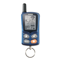
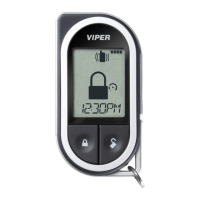
Procedure for teaching transmitters to the system for arming, disarming, and channel functions.
Steps to activate the Vehicle Recovery System (VRS) using the transmitter.