Residential Sliding Gate
Operator
19
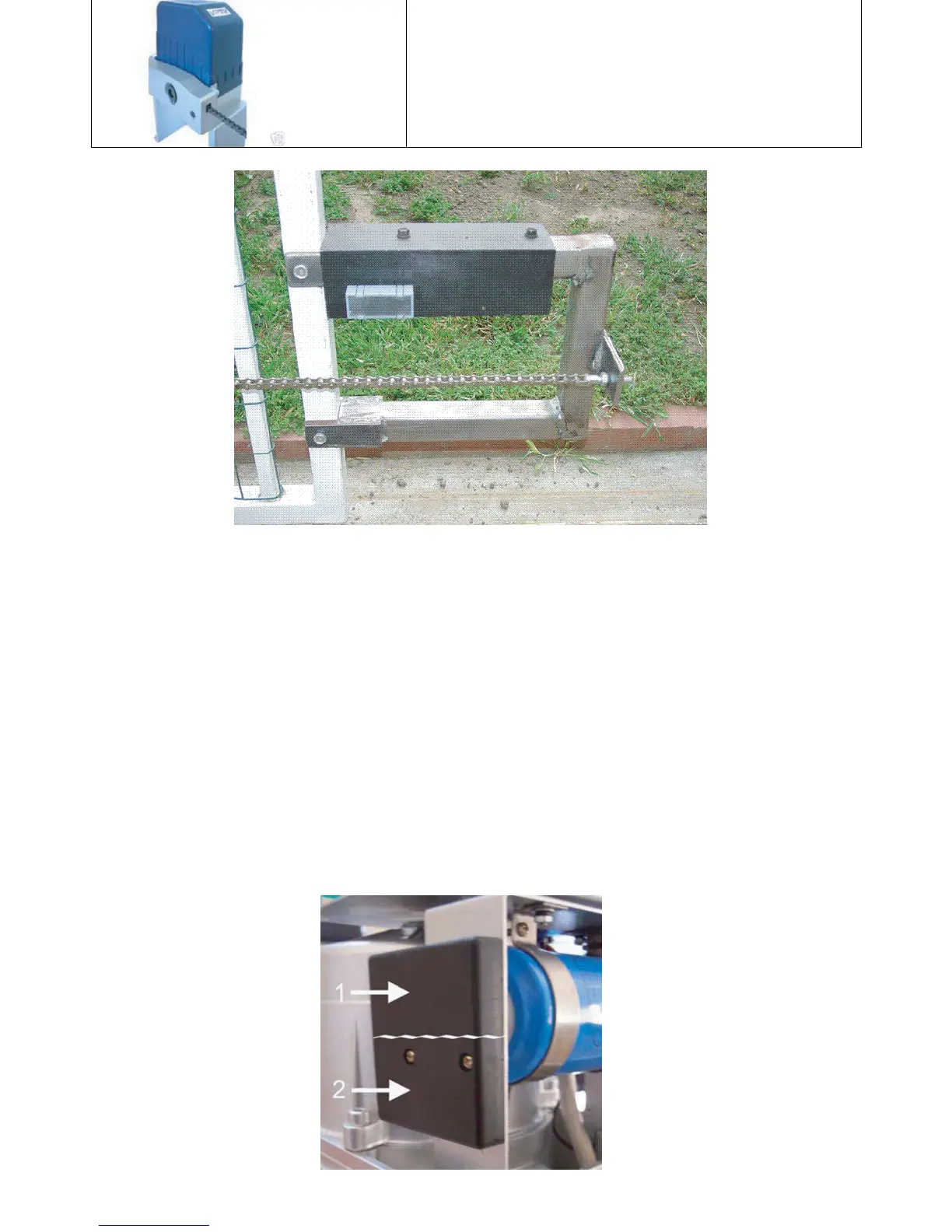
In this configuration, the tail extension was made from the same material as the gate, 1-
½” square tubing, and is 12” long and 10” high. At the right side, the chain bolt plate
was wielded on at the shop as were the two U clamps that attach the extension to the gate
(left). A piece of angle iron was used to support the closing magnet, and mounting holes
were drilled (4) ½ inches apart that allows for the magnet adjustment. Two bolts were
used to attach the angle iron to the extension.
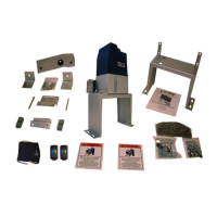
The limit switch sensor is divided into two parts as seen inFigure 8. Limit Switch Sensor
To achieve your open limit, one of the magnets should bemounted so that it is at the same height as
Section 1of the Limit Switch Sensor. To achieve your closed limit, the other magnet should bemounted
so that it is at the same height as Section 2 of the LimitSwitch Sensor.
Note: Make sure that neither
magnets are running in themiddle of the while line on figure 8, otherwise the Control Boardwill think that
the gate is both open and close.
Figure 8