Residential Sliding Gate
Operator
17
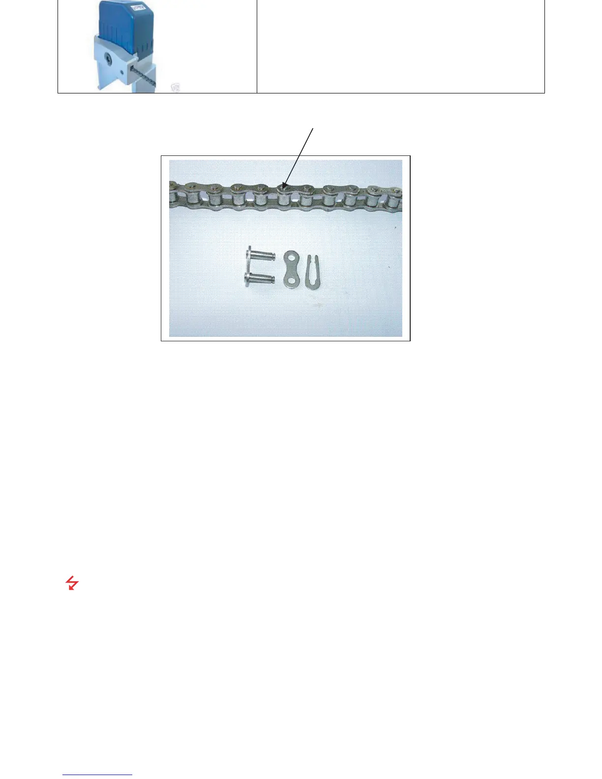
25. Install the chain with a master link to the Chain Box short chain.
26. Stretch the chain to the Chain Bolt and install with a Master Link.
27. Adjust and tighten the Chain Bolt allowing for a 3” sag in the chain spanning the
length of the gate.
28. With the Chain Box Clutch loose, move the gate open and closed. It should slide
smoothly.
29. Install the Magnetic Limit magnets on both ends of the gate. On the opening side of
the gate, the “Open” Magnet is in the Upper position, while the tail end of the gate the
“Close” Magnet is in the Lower position. See Figure 2. Manually open and close the
gate to determine where the magnets are to be mounded on the Gate.
30. Adjust the Magnets so there is ½” clearance from the Magnet to the Gate Opener.
31. Mechanical installation of the Gate Operator is Complete
Gate Operator Electrical Installation
The National Electric Code requires proper electrical connections in wet
locations (outdoors) for all electrical equipment.
The procedures that follow assume that a suitable 120 V AC GFCI Outlet receptacle with
a weatherproof cover is located near the Gate Opener (as shown in Figure 5) that can be
used to connect the Electrical Power to the SLIDE Gate Operator. Please follow the
manufactures installation guide for installing and testing a GFCI receptacle.
1. Ensure that the electricity to the Outlet Box is OFF.
2. Check the Power switch on the Viper Control Board. Switch to the OFF position
“O/I” with “O” switch position down).
File off Chain Rivet here
Punch out pin
.
Discard links
Master Lin