The lock sections include also 12V power connectors. These
connectors provide power to the lock with a current limit of 400mA
for each lock. The slave controller supplies power from a backup
battery if available when the AC power is down. Electromagnetic
locks which constantly draw large currents should use the dry
contact ONLY without connecting the internal power supply. The
same holds true for any other device, which does NOT operate at
12VDC.
If you notice problems with a slave controller operating an EMS
that uses an internal power supply, connect the diode supplied
between + and – of the EMS output (see Panel Wiring Diagram).
D. Controller Configuration
Up to seven AXS-100 slave controllers can be connected to a
Master AXS-100/AXS-100 XT controller using a single twisted
pair cable. Each controller (irregardless of type) provides a
3-connector block for daisy chaining the devices in a bus type
configuration.
Connect terminal B to B and D to D, GND to GND, this way up to
seven slave controllers.
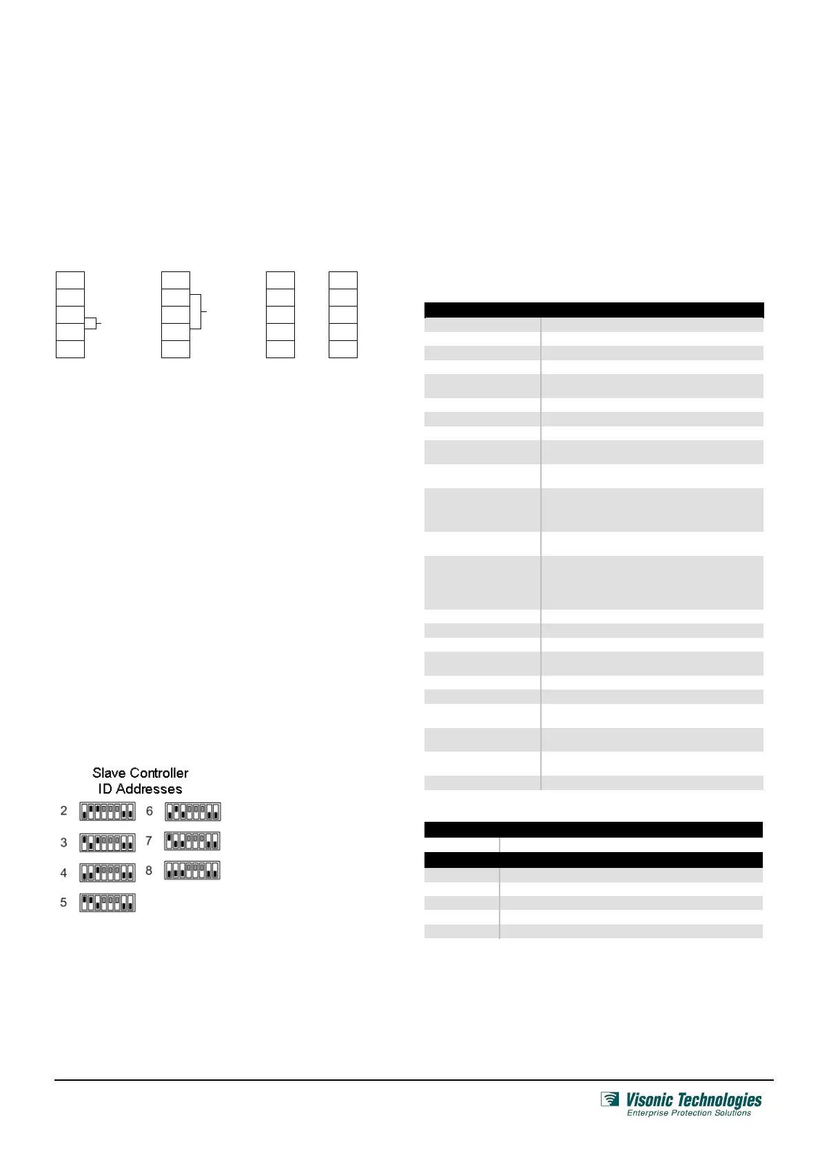
Each AXS-100 Slave Controller has to be assigned a unique ID
address before the device can be fully functional. Since each
RS-485 data loop MUST contain a Master Controller whose ID
address is always set to 1, the ID addresses of the slave(s) units
are range from 2…….8. Addresses
The ID address of the slave controller is configured using the DIP
switches located on the controllers’ circuit board as shown below:
NOTE: A controller’s
ID address MUST be
set before applying
power to the unit.
Also never change the
DIP switch settings
while the slave is
powered up.
NOTE: The ID addresses of the slave controllers need not be in
the physical order of connection.
E. Power Connection
Connect the AC power cable to the power connector on the top
right side of the board.
F. Backup Battery Connection
Connect backup battery to black and red wires on the left side.
3. Maintenance
A. Periodic Check
Once a month, the AXS-100 Slave Controller must be checked by
presenting a tag/card to the reader and verifying that the proper
door is opened
B. Lithium Battery Handling/Disposal
Replace battery with PANASONIC Coin battery type CR2032, 3V
only. Use of another battery may present a risk of fire or
explosion.
Caution: Battery may explode if mistreated, do not recharge,
disassemble or dispose in fire. Dispose any used Lithium battery
only in an approved disposal container.
4. Specifications and Ordering Information
AXS-100 Slave Controller Specifications
Power Input 14 - 16.5 VAC, 50VA
Max. Current 2.5A
Memory Capacity 5,000 access card codes
Event Log 1,000 records per controller
Time Schedules
64 separate schedules
Each key may be assigned to 2 schedules
Dry Contact Relay Max 1A continuous
Doors Controlled Up to 2
Readers Controlled Up to 2 external + 1 internal (for programming)
Slave Controllers per
Master
Up to 7
Inputs (x 2 doors)
Request-to-exit, door position
2 programmable inputs
Outputs
2 lock relays, NO/NC dry contact, 30 VDC 2A max.
1 auxiliary relay, NO/NC dry contact, 30V DC 2A max.
Output power for 2 locks: 10.3 - 12VDC, 400mA max.
2 readers output: 70 mA max.
Anti Passback
(APB) Modes
Local to each controller
Network APB
LED Status Indicators
Green LED #1: Output relay activated (Door 1)
Red LED #2: Power ON
Green LED #3: Ext. battery charged
Red LED #4: Alarm relay activated
Green LED #5: Output relay activated (Door 2)
Construction Metal (indoor usage only)
Color White
Weight 3.8 kilos (8.4 lbs) approximate
Operating Temperature
& Humidity
0° to 50°C (32° to 122°F);
05% to 80% non-condensing
Storage Temperature -20 to +70°C (-4 to 158°F)
Dimensions (L x W x D) 315 x 262 x 74mm (12-3/8 x 10-5/16 x 10-15/16 in.)
Maximum Cable Length
from Controller
5.0 meters (16.4 feet)
Compatible Software
EIRIS V4.6 or higher
AXSalert (all versions)
Standards Compliance
Part 15 of the FCC Rules
RSS-210 of Industry and Science Canada
Warranty One year limited warranty (excluding batter)
Ordering Details
AXS-100 Slave Controller
5-100613 AXS-100 Slave Controller
Compatible System Readers
3-6304-0 RDR-4, Proximity Reader
3-6321-0 RDK-4, Proximity Reader with Keypad
3-6309-0 RDM-4, Proximity Reader, Mullion type
3-6304-1 RDR-4B, Proximity Reader, 12V / 50mA output
3-6304-2 RDR-4B/W, Proximity Reader, White, 12V / 50mA output
Page 4 of 6
DE62821A_V7.0
 Loading...