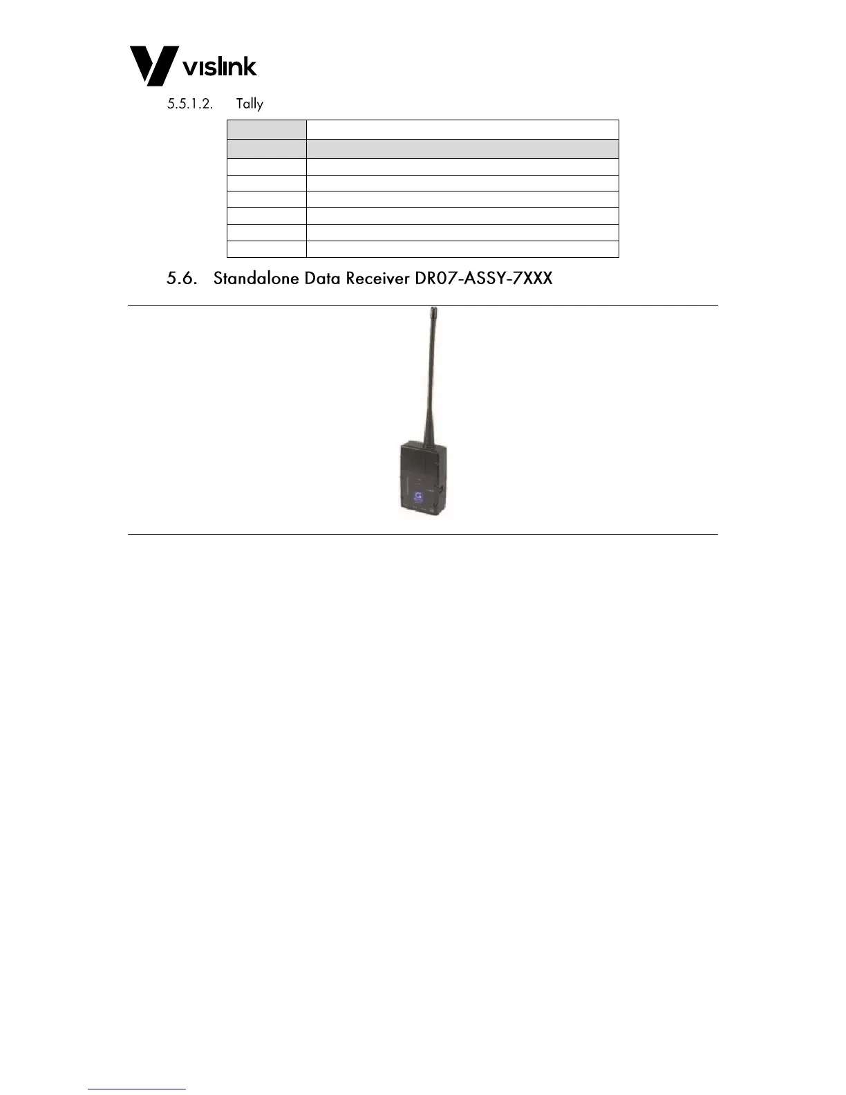
Figure 5-5 Standalone Data Receiver Overview
The Standalone Data Receiver Version07 Unit is small/discrete and easy to mount on many
camera types.
The data connector allows remote connectivity to various camera manufactures and
models using the correct data cable.
The FocalPoint Camera Control system offers control to various camera manufactures and
models using one-way data with the Vislink OCP5 and one-way or return data using any of
the following:
Sony RCP 750/1500/1530
Hitachi RU1500
Panasonic AJRC10G.
Ikegami OCP300/399/100
Panasonic AW-RP50E, AW-HE120G
Grass Valley OCP400
When using the Return Data option, you need to connect the RTN DATA to the User Data
input of the MVL Transmitter.
The DR07 is controlled via a Windows™ PC GUI using TelemetryReceiverInterface.exe. The
Telemetry Receiver Interface user guide is supplied with the GUI when installed.
The configuration cable from the PC connects to a 5-Pin BINDER socket, labelled CONFIG.
 Loading...