Do you have a question about the Vislink FCDT-ASSY-7002 and is the answer not in the manual?
Essential safety guidelines for operating and maintaining the FocalPoint system.
Guidelines for the proper environmental use and protection of the FocalPoint system.
Procedures for the safe and responsible disposal of equipment and batteries.
Information regarding the system's compliance with CE directives and regulations.
Critical safety information on RF exposure and recommended safe working distances.
Details on FCC and Industry Canada compliance for radio frequency emissions.
Overview of how the FocalPoint system components are interconnected.
Information on system frequency settings and available bands.
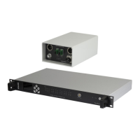
An overview of the Camera Control Interface Unit and its role in the system.
List of camera models supported with specific OCP/RCP interfaces.
Catalog of compatible Operator Control Panels (OCP) for various camera manufacturers.
Technical specifications detailing the unit's hardware and performance characteristics.
Detailed pinout diagrams for all unit connectors, including data and power.
Comprehensive guide to navigating the unit's menu system and options.
Step-by-step instructions for the initial hardware configuration and setup.
Information on system licensing and how to manage activated OCP channels.
Details on connecting multiple interface units for expanded system capability.
Guidance on connecting multiple transmitter units for broader coverage or control.
Configuration steps for enabling and managing return data flow.
Explanation of the Head Scanning feature for multi-transmitter setups.
How to use the 'Send All' function for Sony cameras to transfer settings.
Configuration for automatically turning off RCP display when camera is disconnected.
Procedures for recalling scene files from camera or local memory.
Specific setup steps for Sony PMW-F55 camera with wireless control.
Instructions for the 'Send All' function with Hitachi RU units.
How to connect two interface units using an Ethernet network.
Specific configuration settings for Grass Valley camera and OCP integration.
How to perform 'Send All' operation for Grass Valley cameras.
Setting up OCP channels for transparent data transmission.
Overview of the Camera Control Data Transmitter unit and its function.
Technical specifications of the data transmitter unit.
Identification and function of the unit's controls and indicators.
Explanation of internal rotary switch settings for configuration.
Detailed pinout information for the transmitter's connectors.
Guidance on selecting and connecting appropriate antennas for the transmitter.
General introduction to the Data Receiver modules and their variations.
Technical specifications for the various data receiver models.
Detailed information on the InCam-G camera back receiver.
Connection details for the InCam-G unit.
Detailed information on the InCam-S camera back receiver.
Information on the Clip-on4 Data Receiver module.
Connection details for the Clip-on4 receiver.
Details about the standalone DR07 data receiver unit.
Connection details for the DR07 standalone receiver.
Information regarding the L17xx series built-in data receivers.
An overview of the OCP5 control panel and its purpose.
How the OCP5 can be configured for one-way or two-way data operation.
Information on connecting and controlling tally signals with the OCP5.
Methods for powering the OCP5 control panel.
Options for connecting the OCP5 for data output.
Detailed list of camera control functions available via the OCP5.
How to assign custom functions to the OCP5's OPT button.
Detailed pinout information for the OCP5 rear connectors.
Pinout and function of the OCP5 Mixer connector.
Details on the DC power input for the OCP5.
Information on the USB/Ethernet port functions for monitoring and upgrades.
List of camera types selectable within the OCP5 menu.
A visual guide to the OCP5's menu hierarchy and options.
Examples of the OCP5's main operator and setup screen interfaces.
External camera control cable for Grass Valley LDK Clip-on4.
External camera control cable for Grass Valley LDK DR07.
External camera control cable for Sony Clip-on4 cameras.
External camera control cable for Sony DR07 receivers.
External camera control cable for Hitachi ClipOn4 cameras.
External camera control cable for Hitachi DR07 receivers.
External camera control cable for Ikegami Clip-on4 cameras.
External camera control cable for Ikegami DR07 receivers.
External camera control cable for Panasonic ENG Clip-on4.
External camera control cable for Panasonic ENG DR07.
Cable specifications for connecting Sony RCP to the camera interface.
Cable specifications for connecting Hitachi RU to the camera interface.
Cable specifications for connecting Ikegami OCP to the camera interface.
Cable specifications for connecting Panasonic ENG RCP to the interface.
Cable specifications for connecting Vislink OCP5 to the camera interface.
Cable specs for GV OCP RS232 (non-multiplexing) to interface.
Cable specs for GV OCP RS422 (multiplexing) to interface.
| Brand | Vislink |
|---|---|
| Model | FCDT-ASSY-7002 |
| Category | Control Systems |
| Language | English |