Do you have a question about the Vislink CRIU-ASSY-7004 and is the answer not in the manual?
Ensures awareness of potential hazards during operation and maintenance of the equipment.
Provides safety guidelines on RF exposure and recommends safe working distances.
Warnings for operating radio equipment near blasting caps or in explosive atmospheres.
Technical details of the system's radio specifications.
Transmitter specifications including output power and attack time.
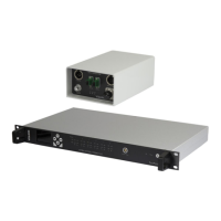
Overview of the FocalPoint Camera Racking system components and connections.
Details on frequency bands, bandwidths, and channel spacing for the system.
List of camera manufacturers and models compatible with the CRIU.
List of compatible Operator Control Panels (OCP) for different camera manufacturers.
Description of front and rear panel controls, indicators, and connections.
Detailed pinout information for various connectors.
Pinout details for the Camera Control Interface Unit's connectors.
Pinout details for the front panel Remote/Data connector.
Pinout details for the rear panel Data connector.
Pinout details for the Expansion connector.
Pinout details for the 15-Way D-Type socket for OCP connections.
Pinout details for the 25-Way D-Type socket for Red Tally connections.
Pinout details for the 25-Way D-Type socket for Green Tally connections.
Pinout details for the 7-Pin LEMO socket for Return Data connections.
Diagram illustrating the menu structure for the Camera Control Interface Unit.
Step-by-step guide for setting up the hardware configuration of the system.
Details on connecting and configuring multiple Interface Units for expanded system control.
Information on connecting multiple Transmitter Units using Expander Modules.
Configuration for one-way or return data using manufacturer OCP/RCPs.
Enables roaming between Transmitter Heads for continuous coverage.
Procedure for sending camera paint configuration settings from Sony RCP to the camera.
Automatic disabling of camera display when connection is lost.
Recalling scene files from camera memory or FocalPoint memory.
Procedure for sending camera paint configuration settings from Hitachi RU to the camera.
Guidelines for connecting Interface Units via Ethernet.
Configuration steps for connecting Data Transmitter Interface Unit via Ethernet.
Overview of Data Receiver modules and their function with cameras.
General specifications for the Data Receiver unit.
| Brand | Vislink |
|---|---|
| Model | CRIU-ASSY-7004 |
| Category | Control Systems |
| Language | English |