EasyManuals Logo

Vislink FCDT-ASSY-7002 User Manual

Vislink FCDT-ASSY-7002
70 pages
To Next Page IconTo Next Page
To Previous Page IconTo Previous Page
Page #40 background imageLoading...
Page #40 background image
User Manual Focal Point
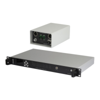
Camera Control Data Transmitter - FCDT-ASSY-7XXX
Issue No: M Page: 32
Ref: FOCL-ASUM-8xxx Copyright © 2017 Vislink plc
Connector/Indicator Area
Function
Front Panel
12 - 24Volt DC input
DC Circuit Breaker
Tx & Rx Fiber connection
3-Pin XLR connection
RF Power output
Status Indicator (Green)
Tx Data Indicator (Amber)
Rx Data Indicator (Amber) Not used
Top
IDX Battery Plater option available
Base
Wedge plate
Table 4-1 FCDT-ASSY7xxx Connectors, Controls, Indicators and Fixings
Mechanical Details
Specification
Size
130mm (W) x 82mm (H) x 210mm (D)
Weight
1.54kg. Approx.
Environmental
Temperature range: - 20° C to +70° C
Table 4-2 Mechanical and Environmental Details
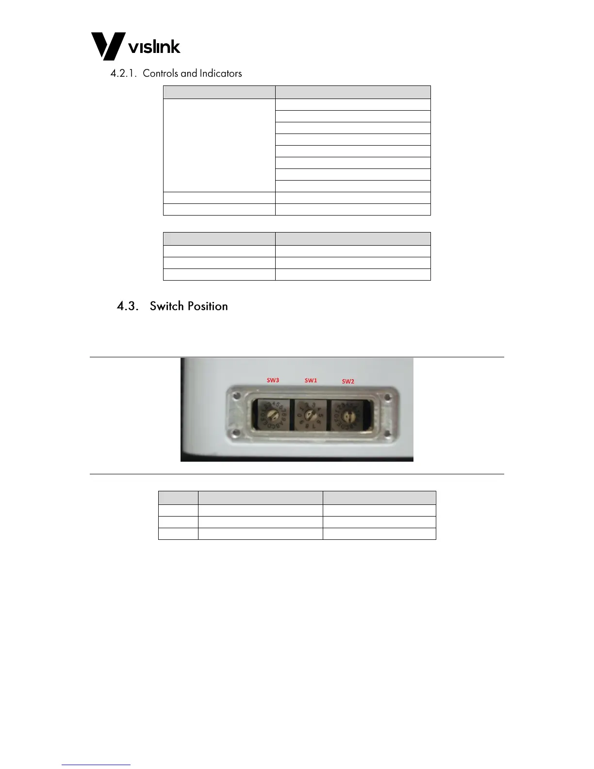
The unit has a set of internal Rotary switches that can be accessed by removing the small
access plate on the side of the unit.
Figure 4-3 FCDT-ASSY7xxx Switch Locations
Switch
Function
Position
SW1
Address (ADDR)
Option for 1 to 8 available
SW2
Channel (RADIO CHNL)
Not used
SW3
Camera Type (CAMERA TYPE)
A RS485 2wire
Table 4-3 Switch Configuration Table
The FocalPoint system is capable of connecting one to eight Data Transmitter units to a
single Control Interface unit. Each unit must have a separate address allocated.
The Data connection is RS485 2-wire only.

Questions and Answers:

Question and Answer IconNeed help?

Do you have a question about the Vislink FCDT-ASSY-7002 and is the answer not in the manual?

Vislink FCDT-ASSY-7002 Specifications

General IconGeneral
BrandVislink
ModelFCDT-ASSY-7002
CategoryControl Systems
LanguageEnglish

Related product manuals