User Manual Focal Point
Camera Control Interface Unit - CRIU-ASSY-7XXX
Issue No: M Page: 13
Ref: FOCL-ASUM-8xxx Copyright © 2017 Vislink plc
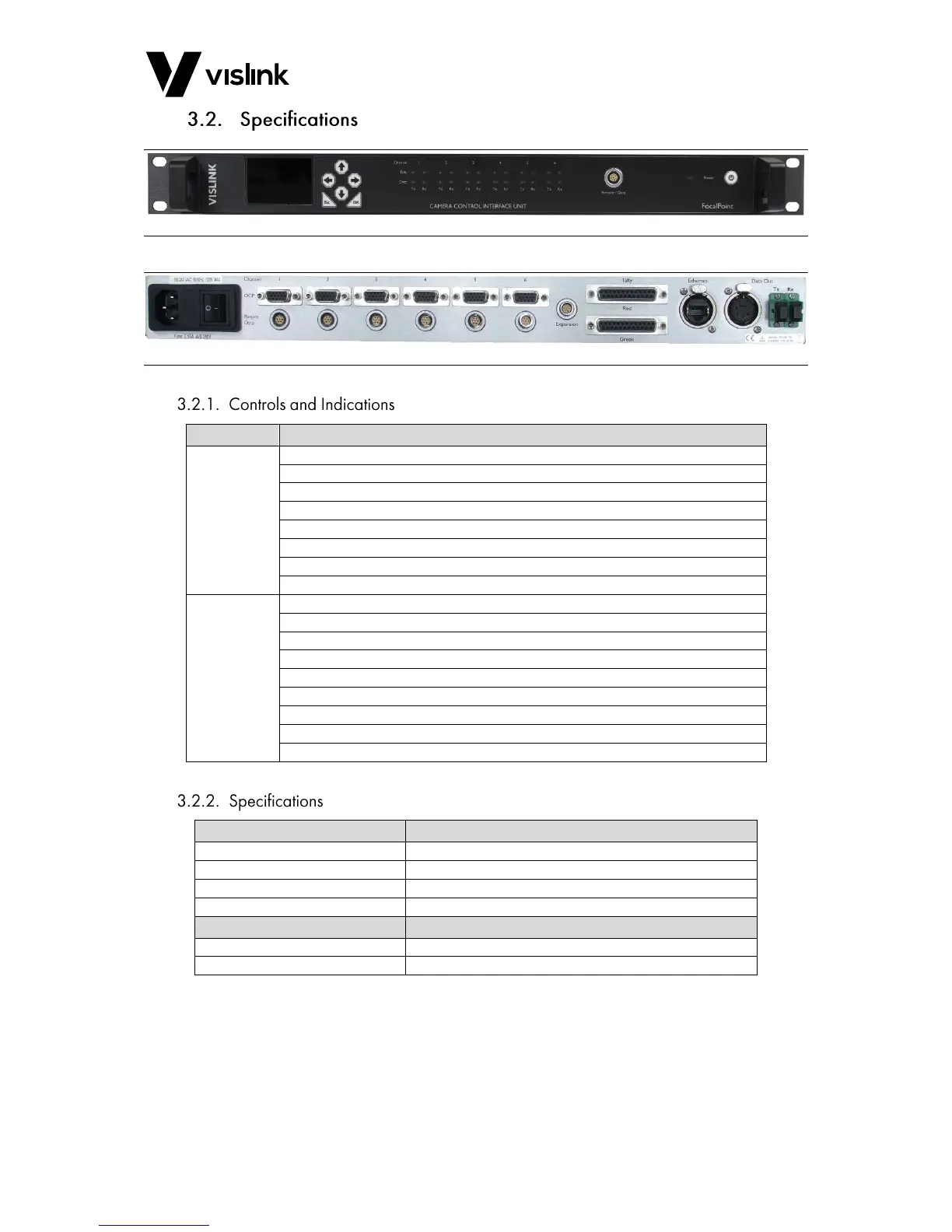
Figure 3-2 Front Panel Overview
Figure 3-3 Rear Panel Overview
Power supply indicator for +12VDC (Red-Standby, Green-On)
Transmit Data activity indicator (Blue)
Receive Data activity indicator (Blue)
Red Tally indicator (Red)
Green Tally indicator (Green)
Soft-start Power ON/OFF switch
Unit menu controls and display
Remote/Data connection for firmware installation and Web-interface control
Power ON/OFF (integrated with IEC connector)
Six Return data connections
25-Way D-Type Red Tally connections (6Dry & 6Wet)
25-Way D-Type Green Tally connections (6Dry & 6Wet)
3-pin XLR Data connection
Expansion connection for additional CRIU or FCDT
Table 3-3 CRIU-ASSY-7XXX Panel Connectors Overview
435MHz – 490 MHz (Other bands available on request)
12.5 KHz / 20.0 KHz / 25.0 KHz
100V – 240V AC 50/60Hz 0.5A max.
Configurable in 0.1 W steps.
Table 3-4 CRIU-ASSY-7XXX Specifications