2.6. Wiring the auxiliary input
Notes:
For UL installations, the device connected to the initiating circuit must be
located in the same room as the transmitter.
For UL installations, connect to UL listed residential burglar alarm
accessories only.
For ULC installations, connect ULC listed products only to the auxiliary
wiring input.
An alarm message is transmitted once the loop is opened or short
circuited.
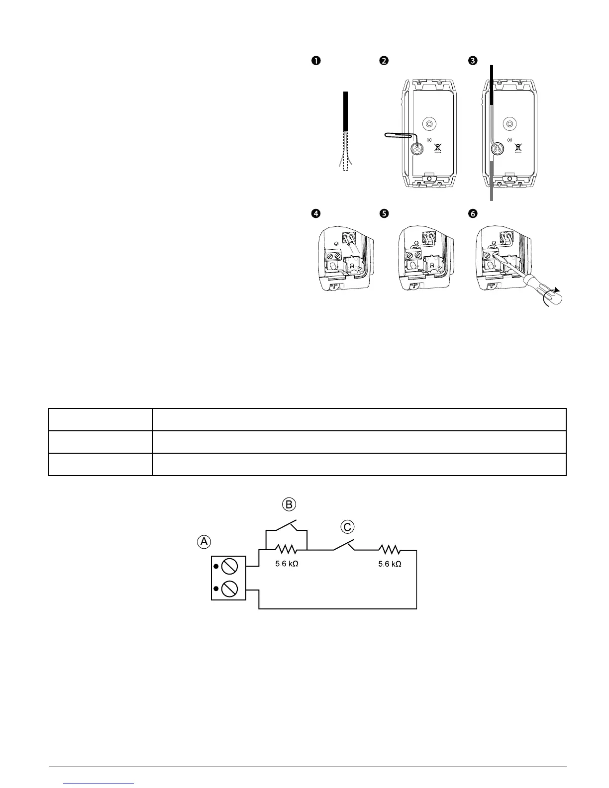
To connect this device with another nearby device via auxiliary input,
complete the following steps:
1. Remove the jacket at the end of the cable to expose the wires within.
2. Perforate the silicon gasket, at the back of the device, with a 0.8 mm
(1/32 in) pin.
3. Pass each wire through an entry hole and out the opposite side.
4. Remove the insulation from the end of each wire.
5. Connect each wire to the relevant terminal, referencing"Auxiliary
wiring options" below.
6. Screw the terminal closed using a flat head screwdriver.
Notes:
Use a 22 AWG AUX cable for this installation.
Use a cable shorter than 3 m (10 ft) for the AUX connection.
Seal the auxiliary wiring gasket with RTV Silicone adhesive sealant.
Figure 9- Auxiliary wiring
2.7. Auxiliary wiring options
You can add more devices to the circuit of the MC-312 PG2 for normally closed, normally open or end of line applications. Each application type is
explained in the table below:
Normally closed (NC) Exclusively use series connected NC sensor contacts if the auxiliary input of the MC-312 PG2 is defined as a normally
closed (NC) type. An EOL resistor is not required.
Normally open (NO) Exclusively use parallel connected NO sensor contacts if the auxiliary input of the MC-312 PG2 is defined as NO type.
An EOL resistor is not required.
End of Line (EOL) For EOL supervision, NC sensor contacts can be used. A 5.6 kΩ EOL resistor may be wired at the far end of the zone
loop.
Note: Figure 10 illustrates a DEOL (Double End of Line) resistor setup, which is available dependent on panel software version.
Figure 10 - DEOL wiring example
A: Terminal B: Alarm C:Tamper
D-307174 MC-312 PG2 Installation Instructions 4