Notes:
l The required battery is CR2032 Lithium 3V, manufactured by VARTA or another UL-recognized manufacturer, purchased from a Visonic-
approved supplier.
l To comply with FCC and IC RF exposure compliance requirements, the device should be located at a distance of at least 20 cm from all persons
during normal operation. The antennas used for this product must not be co-located or operated in conjunction with any other antenna or
transmitter.
l Insert the battery when installing the product but not prior to the installation as this can degrade battery life performance.
1. Insert a “quarter” coin in the slot, as shown in the drawing, and flex to remove the cover
- or, if a “quarter” coin is not available -
Insert a 4 mm flat screwdriver into the slot of the plastic cover, as shown in the drawing, and flex the slot to open that side of the plastic cover.
2. Insert the screwdriver into the slot on the other side of the plastic cover and repeat the procedure, and then remove the cover.
3. Insert the battery at an angle (see drawing) while observing battery polarity and then press down on the battery.
Caution! Risk of explosion if battery is replaced by an incorrect type. Dispose of used batteries according to the manufacturer's instructions.
4. Peel away the release liners from the two strips of double-sided adhesive tape and attach to the device and magnet.
5. Align the device with the magnet according to the location marks and fasten the device and magnet to the mounting surface. The transmitter
should be mounted on the fixed surface and the magnet on the moving surface.
6. For the 433 or 868 MHz installer models, ensure that the heads of the tightened screws are flat perpendicular to the device surface.
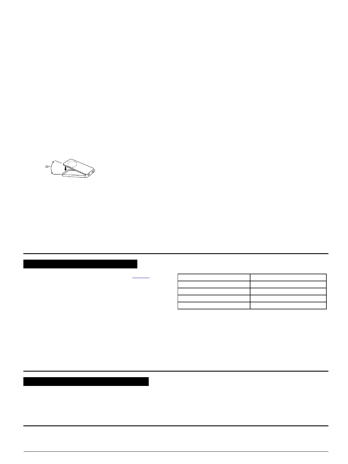
To close the cover complete the following steps:
l Insert the two teeth on the front cover into the corresponding slots on the base.
l When the cover is approximately at a 30 degree angle to the base, push into place until you hear a click.
Figure 3: Closing the cover
2.2. Enrollment
Refer to the PowerMaster panel's Installer Guide and follow the procedure under the "02:ZONES/DEVICES" option of the Installer Menu. The
following is a general description of the steps through the panel menu:
1. 02:ZONES/DEVICES
2. ADD NEW DEVICES > MODIFY DEVICES
3. ENROLL NOW or > ENTR ID:XXX-XXXX
4. Z06:Contact Sens > ID No. 104-XXXX
5. Z06:LOCATION > Z06:ZONE TYPE > Z06:SET CHIME > Z06:DEV SETTINGS
3. LOCAL DIAGNOSTICS TEST
Before testing, separate the base from the cover (see Figure 2).
A. Put back the cover to return the tamper switch to its normal
(undisturbed) position.
B. Momentarily open the door or window and verify the red LED blinks,
indicating detection.
C. After 2 seconds one of the LEDs blinks 3 times.
The following table indicates received signal strength indication.
LED response Reception
Green LED blinks Strong
Yellow LED blinks Good
Red LED blinks Poor
No blinks No communication
Important! Reliable reception must be assured. Therefore, "poor" signal
strength is not acceptable. If you receive a "poor" signal from the detector,
re-locate it and re-test until a "good" or "strong" signal strength is received
(in regions requiring UL-compliant installation, only “strong” signal
strength is permitted).
Note: It is recommended to have a "strong" signal strength and you must
verify the signal strength using the control panel's diagnostic test. For
detailed Diagnostics Test instructions refer to the control panel Installer
Guide.
4. MISCELLANEOUS COMMENTS
Visonic Ltd. wireless systems are very reliable and are tested to high standards. However, due to low transmitting power and limited range (required by
FCC and other regulatory authorities), there are some limitations to be considered:
A. Receivers may be blocked by radio signals occurring on or near their operating frequencies, regardless of the digital code used.
B. A receiver responds only to one transmitted signal at a time.
C. Wireless devices should be tested regularly to determine whether there are sources of interference and to protect against faults.
D-304535 MC-302V PG2 Installation Instructions 2

 Loading...