2 DE3592
ENVIRONMENTAL
RFI Protection: >20 V/m up to 1000 MHz.
Operating Temperatures: -10
°C to 50°C (14°F to 122°F).
Storage Temperatures: -20
°C to 60°C (-4°F to 140°F).
Compliance with Standards: Designed to meet FCC Part 15
and Directive 1999/5/EC of the European Parliament.
PHYSICAL
Size
(H x W x D): 94.5 x 63.5 x 53.0 mm (3-11/16 x 2-1/2 x 2-1/16”).
Weight (with battery): 70 g (2.5 oz).
Color: White.
PATENTS: U.S. Patents 5,693,943
z 6,211,522 z D445,709
(another patent pending).
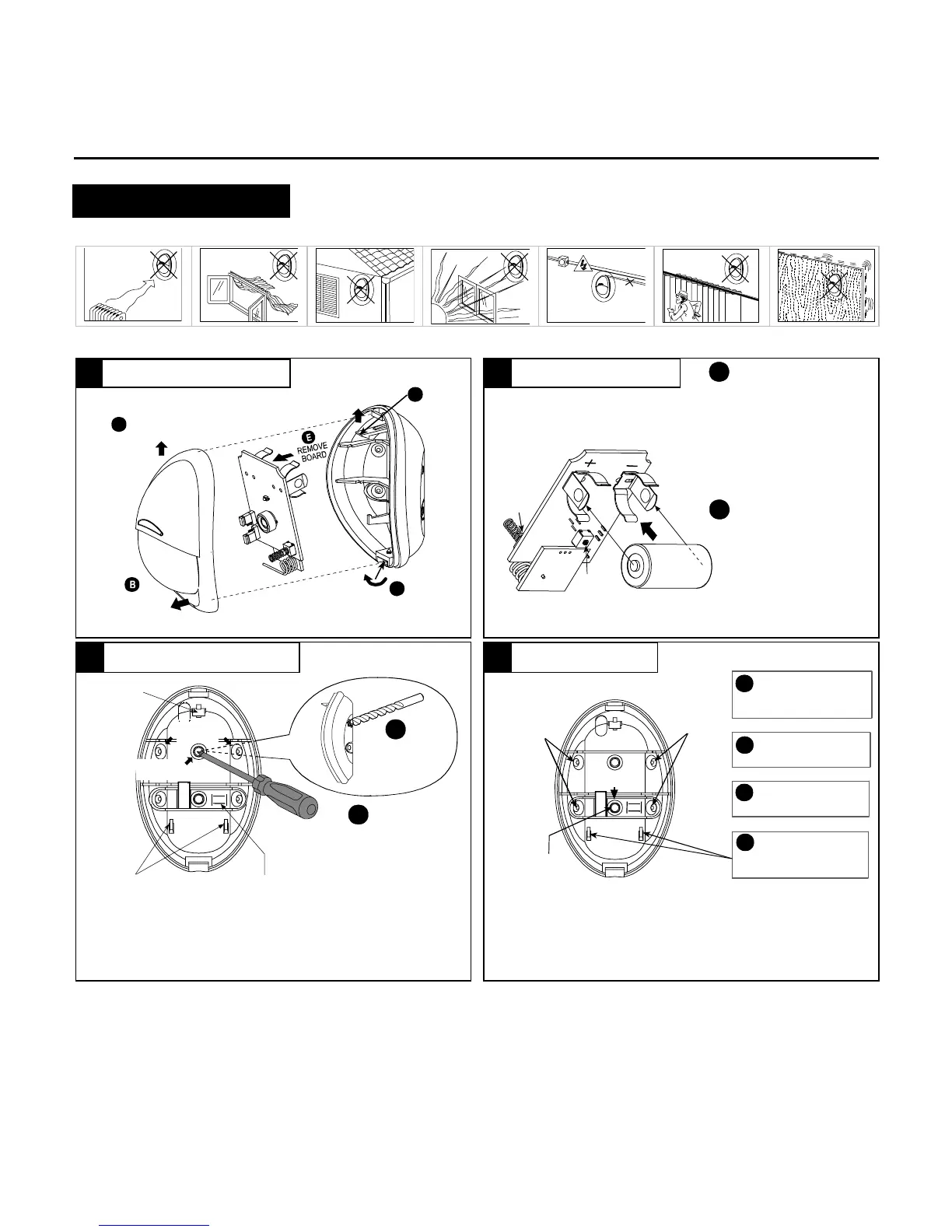
3. INSTALLATION
3.1 General Guidelines
3.2 Illustrated Installation Procedure
FLEX
CATCH
OUT
D
PULL OUT LOWER
EDGE OF COVER
LOOSEN
SCREW
A
C
SHIFT COVER
UP TO FREE
TOP TOOTH
AND
REMOVE
COVER
RESET:
With the battery in
place, press both tamper
switches simultaneously
and release them. The
LED at the front will flash
for about 2 minutes until
the detector stabilizes.
Note: The de]tector transmits
a low battery signal upon
detection of low battery.
Note: It is recommended to wait
about 1 minute before inserting
the new battery.
A
B
BACK
TAMPER
SWITCH
(OPTION)
FRONT
TAMPER
SWITCH
OBSERVE
POLARITY !
ENROLL:
Approach the
control panel and enroll the
detector’s ID into the control
panel’s memory as shown in
the panel’s installation
manual. When required to
transmit, press both tamper
switches again and release
them.
You may enroll the detector’s
ID while the detector’s LED
flashes.
USE A SCREWDRIVER TO PIERCE
SURFACE OR CORNER KNOCK-
OUTS, AS REQUIRED.
A
USE A LARGE
DIAMETER DRILL
BIT TO DE-BURR
THE OTHER SIDE
B
SUPPORTS
FOR BOTTOM
EDGE OF PCB
CORNER
(2 OF 4)
SURFACE
(1 OF 2)
BREAK-AWAY
SEGMENT (BACK TAMPER
SWITCH ACTUATOR - OPTION)
TOP
CATCH
FOR PCB
Attention! Lean the rear part of the break-away segment against a
piece of wood while piercing its knockouts.
B
INSERT TWO DOWELS AND
C
INSERT THE BOTTOM EDGE
D
MARK TWO DRILLING
A
SINGLE-
SIDE, 45°
ANGLED
MOUNT
SURFACE
MOUNT
(1 OF 2)
ATTACH THE BASE TO THE
WALL WITH TWO SCREWS.
OF THE LARGE P.C. BOARD
UNDER THE TABS & PRESS
THE TOP EDGE IN.
POINTS AND DRILL HOLES
IN WALL.
SINGLE-
SIDE, 45°
ANGLED
MOUNT
BREAK-AWAY
SEGMENT
FOR TAMPER PROTECTION,
THE BREAK-AWAY SEGMENT
MUST BE ATTACHED TO
WALL.
1.8 - 2.4 m (6 - 8 ft) above ground
Recommended height up to 2.1 m (7 ft)
Attention!
The unit has a back tamper switch (option) under the PCB. As
long as the PCB is seated firmly within the base, the switch will be pressed
against a metal spring piece attached to the base.
Be sure to fasten the break-away segment to the wall with the screws
going through the metal spring and break-away base segment
. If the
detector is forcibly removed from the wall, this segment will break away
from the base, causing the tamper switch to open and send a tamper alarm.
1
Disassemble the unit
2
Install the batter
 Loading...