STEREO
CHORUS
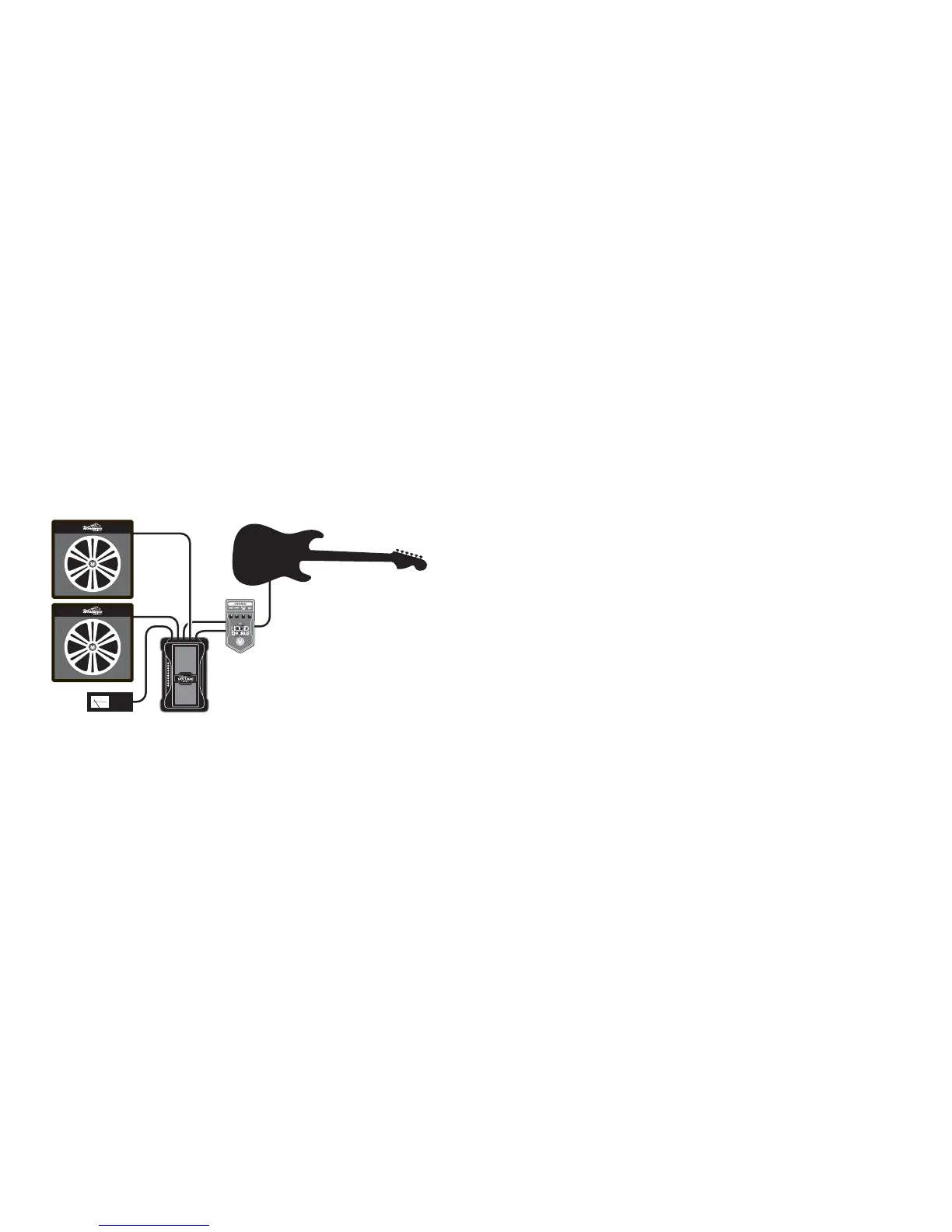
STEREO VOLUME CONTROL
If you plug a signal into Input 1 and Input 2, then
the signal from Input 1 comes out on Output 1 and
the signal from Input 2 comes out on Output 2.
Both Output 1 and Output 2 have their level controlled
by the rocker in unison – it’s a stereo volume pedal
now. So you can plug your guitar into, for instance,
a stereo chorus, then run the stereo chorus output
into the two inputs, and out to two amps.
You can plug in two guitars using this configuration
and switch between the two without unplugging.
EASY POT REPLACEMENT
Over the years, guitar players have used their volume pedals enough to simply wear out the control pots. This leads to crackling,
hiss, dropouts and similar problems. We wanted the Visual Volume pedal to be easy to service, so we made the control pot easy
to remove and replace. Replacement pot kits to restore this to like-new performance are available from Visual Sound.
Many owners will be able to replace their own pot assemblies without taking it to a service technician.
BATTERY REPLACEMENT
Visual Volume uses a standard 9V alkaline battery. To replace the battery, remove the four screws holding the bottom cover
on and remove the battery from the battery compartment. Replace it with a fresh battery, and put it back in the compartment.
Be sure to place the wires from the battery clip in the small notch on the battery compartment so they do not get pinched
between the battery compartment and the bottom of the pedal while the pedal is being used. Better yet, get a 1 SPOT to power
all your pedals and don’t worry about buying batteries ever again!
INTERNAL PEDAL ADJUSTMENTS
The remaining features are controlled from inside the unit. You can remove the bottom plate by removing the four screws
that secure it to the main housing. Looking inside, you should see an internal layout as diagrammed on the following page.
Cable from the jacks and power connector has been left out of the drawing so you can see the other bits more clearly.
 Loading...