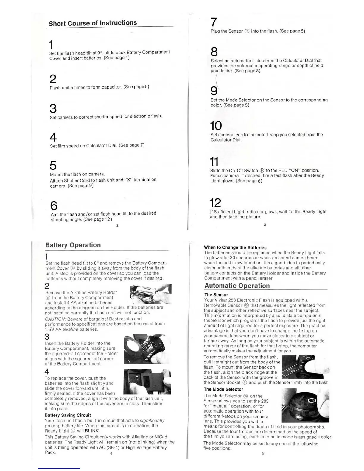
Short Course of Instructions
1
Set the flash head tilt
at
O
~
,
slide back Battery Compartment
Cover and inse
rt
batteries. (See page 4)
2
Flash unit 5 times \0 form capacitor. (Sec page 8)
3
Set camera to correct shutter speed for electronic flash.
4
Set film speed on Calculator Dial. (See page 7)
5
Mount the flash
on
camera.
Attach
Shutler Cord to flash unit and " X" terminal
on
camera. (See page 9)
6
Aim t
he
flash and
/o
r set flash head tilt to the desired
shooting ang le.
(See page
12
)
Battery
Operation
1
Set the flash head tilt to 0
0
and remove the Battery Compart-
ment Cover
® by sliding it away from the body of the flash
unit, A stop is provided on
th
e cover
so
you can load the
batteri
es
without
comp
letely removing the cover
if
desired.
~
'mo"
'h'
A''''jo,
Bot''''
Hold"
~~
@ from the Ballery Compartment
..
'\
..
and
install 4 AA alkali
ne
batteries ,
....
.......
according to the diagram
on
the Holder, If the batteries are
not
installed correctly the
Hash
unit will not functi
on,
CAUTiON; Beware of bargainsl Best results and
performance to specifications are based
on
the use of fresh
I .
SV
AA
alkaline baueries.
3
Insert the Battery Hotder into the
Battery Compartment. making sure
the
sQua
red-olf corner of the Holder
aligns with the
squared-off corner
of the Battery Compartment.
4
To
replace the cover. push the
balleries into the flash slightly and
slide the cover forward until it
is
firmly seated. If the cover has been
completely rerr.oved, align it with the body
01
the flash unit,
making sure the edges
01
the cover are in slots. Then slide
it into place.
Ballery
Saving
Circuit
Your
Hash
unit has a built-
in
circuit that acts to significantly
prolong bal1ery tife. When this circuit is in operation, the
Ready
light
@ will BLINK.
This
Ba11ery
Saving Circuit only works with Alkaline or NiCad
balleries. The Ready
light
will rema
in
on
(not blinking) when the
unit
is
being operated With
AC
(SB-4) or High Voltage Ballery
PaCk
. 4
7
Plu
g the Sensor @ into the flas
h,
(See pageS)
8
Select
an
automatic f-stop from
th
e Calculator Oi
althat
provides the automatic operating range
or
depth of field
you des ir
e.
(S
ee
page 8)
J
Set
the Mode Selector
on
th
e
Senso~
to the corresponding
color.
(See page
S)
10
Set camera lens to the auto
I-s
top you
se
lected from the
Calculator Dial.
11
Slide the
On-Olf
Switch ® to
th
e
RED
"
ON
" position.
Focus camera.
II
desired,f
i
re
a test flash alter the Ready
L
ig
ht
glows. (See page
6)
12
!I
Sullicient
light
Indicator glows,
wa
it for the Ready
ligh
t
and then take the
pic
ture.
,
When to Chan
ge
the B
aller
ies
The batteries should be replaced when the Ready Light lails
to glow alter
30 seconds or when no sound can be heard
when the
un
it is sw
it
ched on.
Irs
a good idea to periodically
clean both ends
01
the al
ka
line batte ri
es
and all other
battery contacts on the Battery Holder and inside
thE::
Battery
Compartment
wllh a pencil eraser.
Automatic Operation
Th
e Sensor
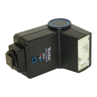
Your Vivita r 283 Electronic Flash
is
equipped with a
Re
moftable Sensor ® that measures
the
light reflected from
the
sueject and other reflective surfaces near the subject.
This
inlormallOn is interpreted
by
a solid stale computer
in
the Sensor which programs the Ilash
to
provide just the right
amount of light required for a perfect exposure. The practical
advantage is that you
don't
have
to
change lhe I-stop
on
your camera lens
wh
en you move closer to a subject
or
larther away, As long as your subject is within the automatic
operating range of the flash
lor
that I-stop, the computer
au
tomatically makes the adjustment for you.
To remove the
Sensor from the
p'.lll it straight out from the body
flash .
To
mount the Sensor back
on
the flash, align the
black
ridge at the
back of the
Sensor with the groove in
the
Sensor Sock
et
CD
and push the Senso
rl
irmly into the flash.
Th
e Mode
Se
t
ector
The Mode Selector ®
on
the
Sensor allows you to set the 283
lor " manual"
opelatiofl,
or
for
au
tomatic operation with
lour
different I-stops
on
your camera
lens, This provides you with a
means for controlling the depth
of field in your photographs.
Because the four
f·stops
are determined
by
the speed of
the
fil m you are using, each automatic mode isassi
gneda
color,
The Mode
Se
lector may be
set
to
anyone
of the following
five positions'
 Loading...