VIVOTEK
User's Manual - 7
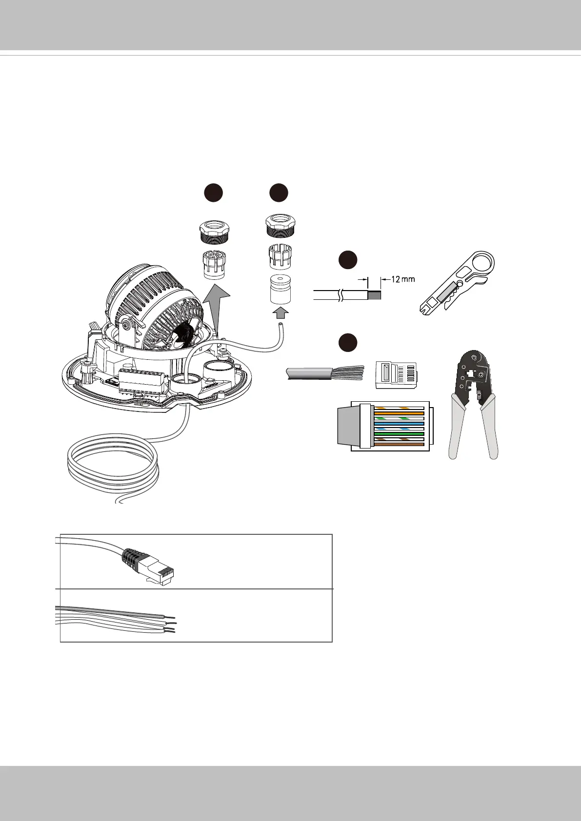
3. Loosen and remove the waterproof connectors.
4. Insert an Ethernet cable through the cable gland, and the rubber seal.
5. Remove part of cable sheath.
o
O
g
B
b
G
br
BR
1
2
3
4
5
6
7
8
o: white/orange stripe
O: orange solid
g: white/green stripe
B: blue solid
b: white/blue stripe
G: green solid
br: white/brown stripe
BR: brown solid
5~6.3mm
DI/DO: 1.8~2.1mm
3 4
5
6
6. You will need an RJ45 crimping tool to attach the Ethernet wires to a connector. When
done, connect the cable to the camera’s Ethernet RJ45 socket.
 Loading...