VIVOTEK
User's Manual - 11
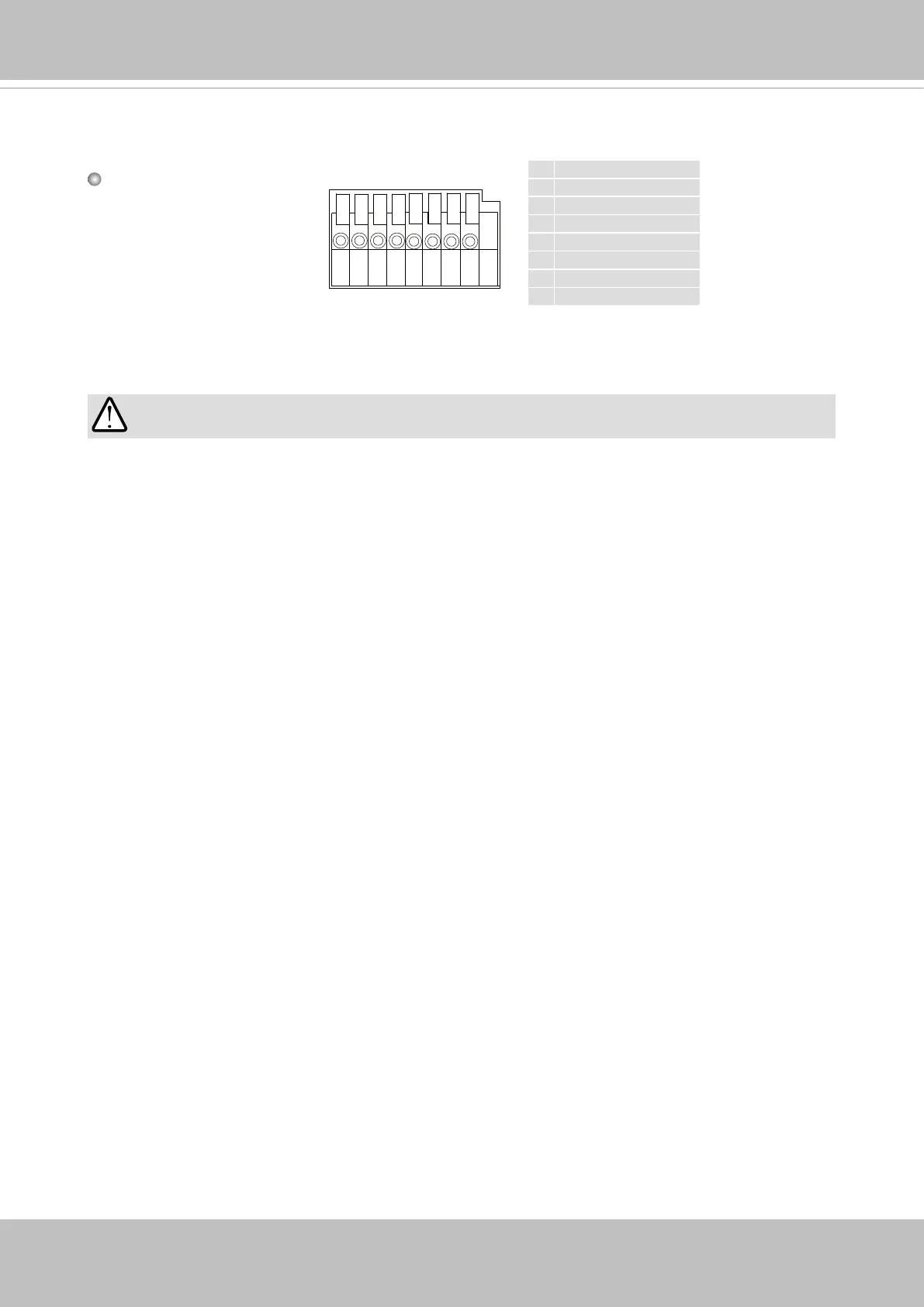
Connect power lines and if you have external devices such as sensors and alarms, make
the connection from the general I/O terminal block.
87654321
Pin Denitions
1 DC 12V-
2 DC 12V+
3 AC24V_2
4 AC24V_1
5 DI- (GND)
6 DI+
7 DO-
8 DO+ (+12V)
Power and IO cables pass through a waterproof connector. The Ethernet cable should be
routed through a rubber seal plug. All cables are user-supplied.
1. The DO 12V output is not available when powered by PoE. It is available with 12V or 24V
power source.
2. The max. load for power output pin 8, 12V DO, is 50mA.
IMPORTANT: