VIVOTEK
8 - User's Manual
87654321
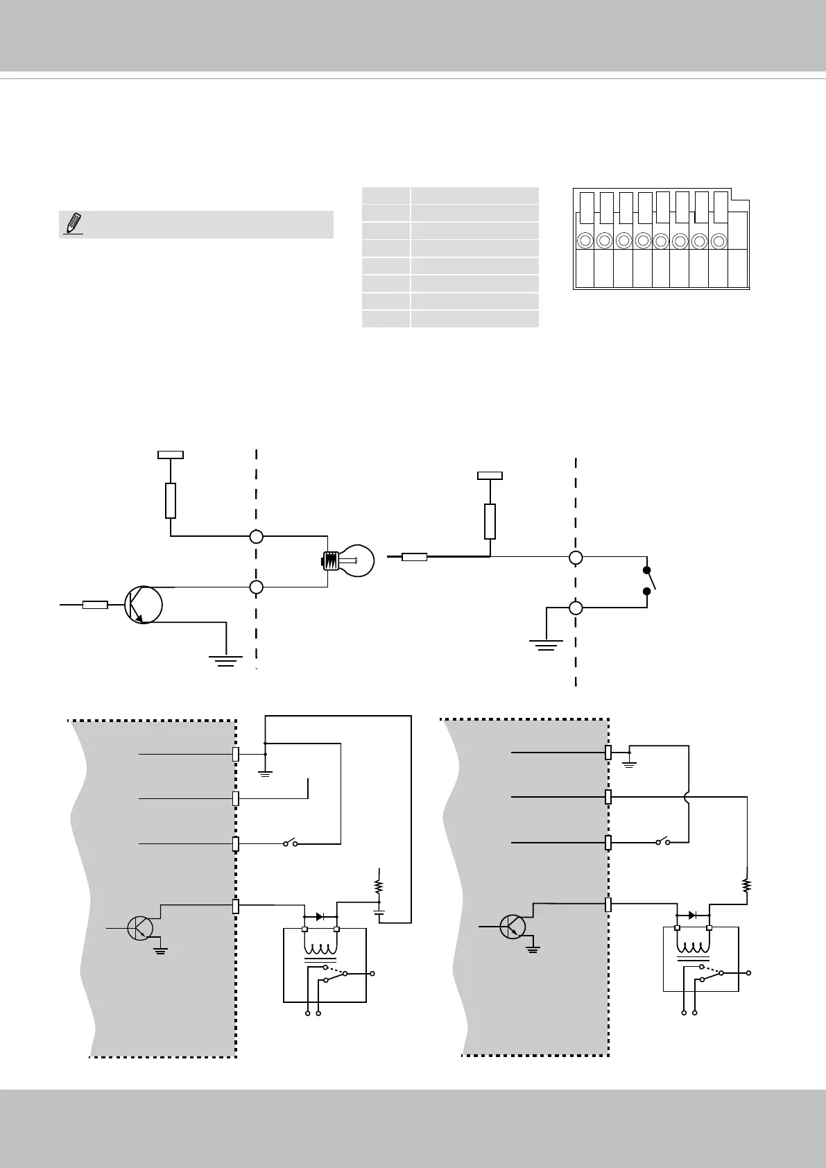
DI/DO Diagram
Please refer to the following illustration for the connection method.
1 DC 12V-
2 DC 12V+
3 AC24V_2
4 AC24V_1
5 DI- (GND)
6 DI+
7 DO-
8 DO+ (+12V)
The max. load for power output pin 8,
12V DO, is 50mA.
NOTE:
GND
Camera Power
Input
Output
+12
VDC
Max.
VDC
Switch
BJT transistor
GND
Camera Power
Input
Output
+12
VDC
VDC
Switch
BJT transistor
Relay
Relay
+12V
Digital output
PIN 8
Power+12V
PIN 7
Digital input
PIN 6
Ground
PIN 5
General I/O Terminal Block
This Network Camera provides a general I/O terminal block which is used to connect external
input / output devices. The pin denitions are described below. The 24V AC can be used as an
alternate power source.