VIVOTEK
8 - User's Manual
1
2
3
4
5
6
7
8
9
10
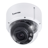
# Name
1 EXT_MIC_N
2 EXT_MIC_P
3 Audio_out-
4 Audio_out+
5 DI-
6 DI+
7 DO-
8 DO+
9 12V DC-_IN
10 12V DC+_IN
7
7. If applied, connect DI/DO wires, 12V DC power, or audio wires to the terminal block.
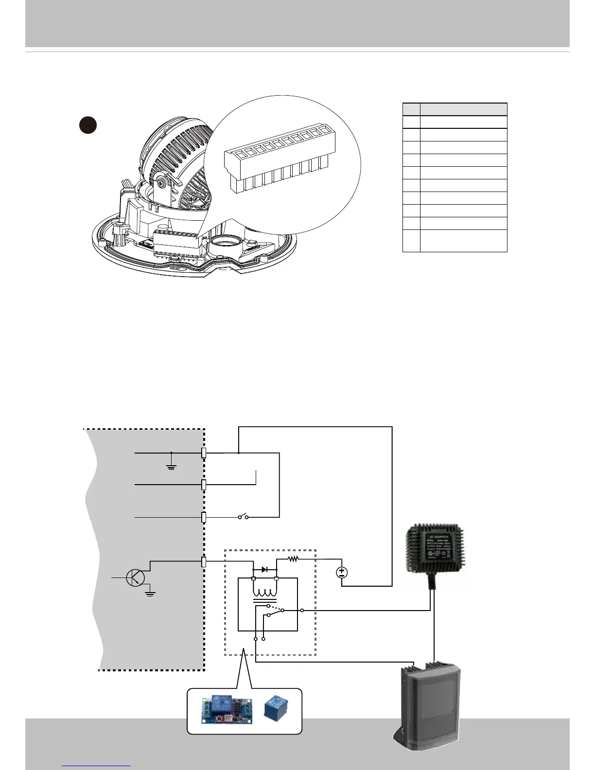
1. The DO+ pin provides a 12V output, and the max. load is 50mA.
2. The max. voltage for DO- pins is 80VDC (External power).
In order to control AC devices, the following diagram can be taken into consideration.
This diagram uses a relay to control the ON/OFF condition of the AC device.
3. An external relay can be triggered by using the DO+ or by an external power source,
depending on the type of relay you use.
4. In case of using an individual relay (instead of using a relay module), for protection
against voltage or current spikes, a transient voltage suppression diode must be
connected in parallel with the inductive load.
DI-
DO+
DI+
DO-
External
power source
VDC
Switch
BJT transistor
Relay
AC
Source
NO NC
External
device