EN - 7
English
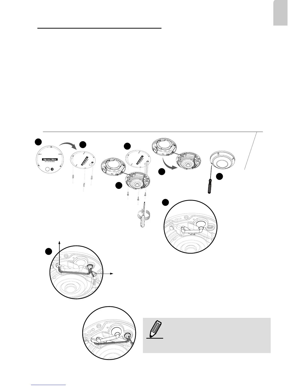
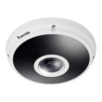
Ceiling/Wall Mount without Mounting Plate
(Choose this mounting type if you would like to feed the cables form the bottom
of the camera)
NOTE:
Arrange the cables neatly to avoid
getting in the way when the dome
cover is attached.
Pin Header (J7)
Pin Header (J6)
1
2
3
8
9
4
5
6
1. Attach the supplied alignment sticker for camera base to the ceiling/wall.
2. Using the three circles on the sticker, drill three pilot holes into the ceiling. Then hammer the
three supplied plastic anchors into the holes.
3. Drill a cable hole on the ceiling/wall, and feed the cables through the hole.
4. Connect the Ethernet cable to the socket.
5. Connect the two white pin header connectors to the J6 and J7 connectors.
6. Secure the camera base to the ceiling/wall with three supplied screws.
7. You will nd a moisture absorber attached to the camera. Replace the moisture absorber includ-
ed in the camera with the one shipped within the accessory bag.
8. Attach the dome cover.
9. Secure the four screws with the supplied stardriver. Make sure all camera parts are securely in-
stalled.