VIVOTEK
User's Manual - 11
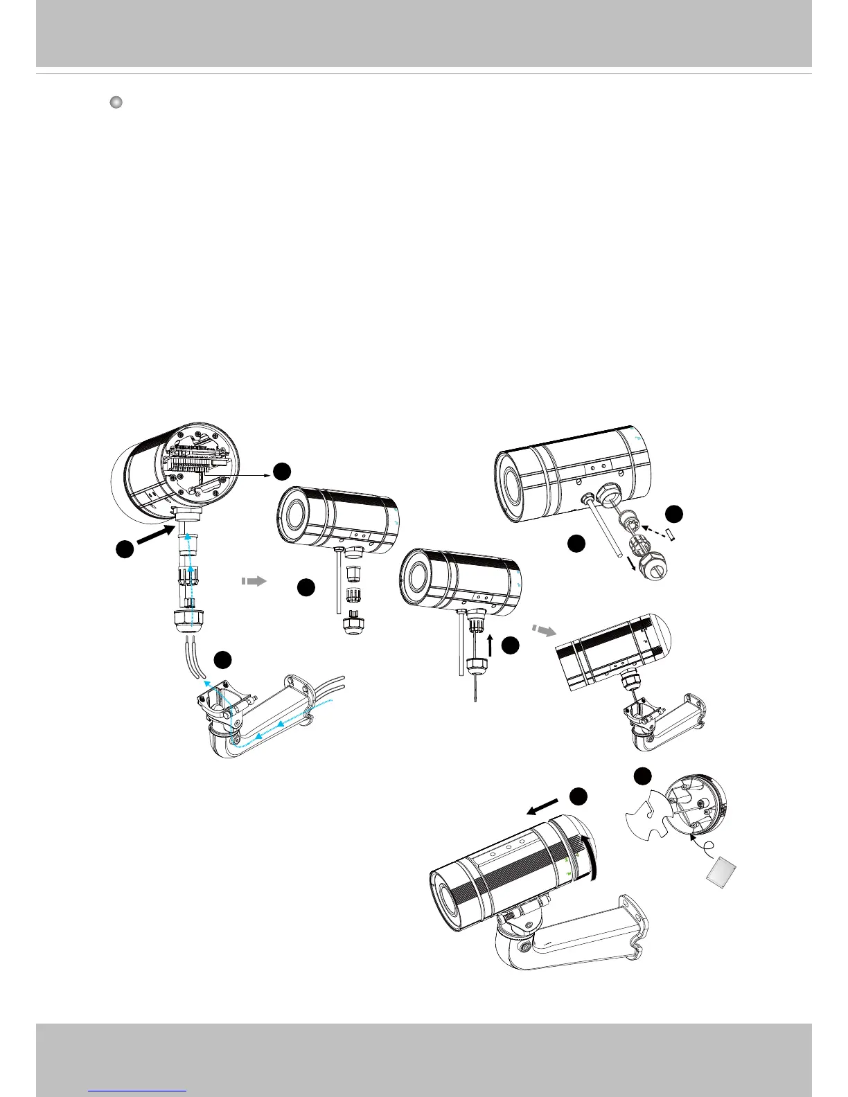
1. Disassemble the components of the waterproof connector into part (A) ~ (E) as shown
above.
2. Open the rear cover of the Network Camera.
3. Remove the rubber stopper from the bottom of the Network Camera and secure the
screw nut (A) tightly.
4. You may choose to use AC24V or DC12V inputs as power source, please feed the
power lines through the wall mount bracket and the waterproof connector (E --> D -->
B --> A) as illustrated below. Pass power lines through the rubber seal (B) and then
connect the power lines to the terminal block.
5. If you have external devices such as sensors and alarms, feed the cables through the
wall mount bracket and the waterproof connector (E --> D --> B --> A) as the illustration
shown below. Then refer to the pin denition to connect them to the general I/O terminal
block. Note: The recommended cable gauge is 2.0 ~ 2.8 mm.
6. Push the seal (B) into the housing (D).
7. Insert the seals (C) into the empty holes on the seal (B) to avoid moisture.
8. Secure the sealing nut (E) tightly.
Assembling Steps
9. Open the aluminum foil vacuum bag
and take out the desiccant bag. Attach
the desiccant bag to the inner side of the
rear cover, to under the insulation pad,
and then tighten the rear cover. (Please
replace the desiccant bag with a new one
whenever you open the rear cover.)