EN - 4
Network Deployment
3
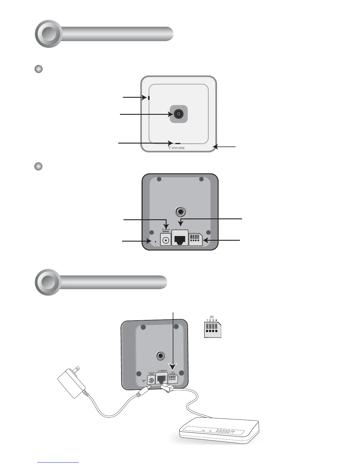
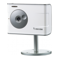
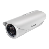
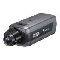
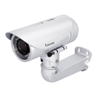
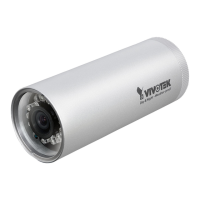
Physical Description
2
Front Panel
Back Panel
Status LED
P
Privacy Button
Lens
Built-in Microphone
ETHERNET
RESET
IO
1234
General I/O
Terminal Block
Recessed Reset Button
Power Cord Socket
Ethernet 10/100
RJ45 Socket
POWER
COLLISION
LINK
RECEI V E
PARTITION
1
2
3
4
5
3. Connect the supplied power cable
from the camera to a power outlet.
2. Connect the camera to a switch
via Ethernet cable.
● Use Category 5 Cross Cable
when Network Camera is directly
connected to PC.
1. If you have external devices such as sensors and alarms,
make connections from general I/O terminal block.
1: Power
2: Digital output
3: Digital input
4: Ground