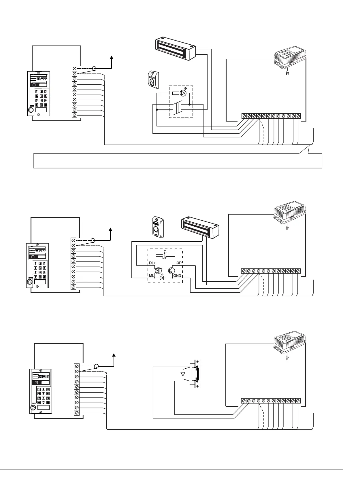
EXAMPLES OF WIRING DIAGRAMS
1
2
3
6
5
4
10
9
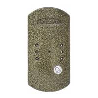
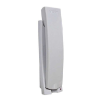
DOORSTATION
BVD 43F(FCPL)-3
SP+ 2
SP- 3
MIC 5
RX 6
GND 1
+E 4
VG 9
VO 10
7
TX 7
8
PRG 8
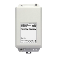
to commutator
distribution amplifier
/
Figure 6 Doorstation
, and button
- -343
М
BVD F(FCPL) BUD-302M (K-20, K-80)
EXIT 300
with Control Unit ,
Electromagnetic Lock VIZIT-ML240-40
Red
Green
White
Black
Blue
Electromagnetic
lock VIZIT-ML240-40
Button
МEXIT 300
RX
SP-
TX
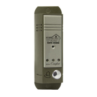
CONTROL UNIT
BUD-302М ( -20, -80)KK
4
5
+DL
-DL
OP
TM
SP+
GND
MIC
+E
DSD
1
3
62 7
Figure Doorstation with Control Unit ,
Electromagnetic Lock , and button
-343BVD F(FCPL) BUD-302M (K-20, K-80)
VIZIT-ML240-40 EXIT 500
7-
Figure -8 Doorstation with Control Unit ,
and electromechanical lock / strike
-343BVD F(FCPL) BUD-302M (K-20, K-80)
Electromagnetic
lock VIZIT-ML240-40
RX
SP-
TX
4
5
+DL
-DL
OP
TM
SP+
GND
MIC
+E
DSD
1
3
62 7
CONTROL UNIT
BUD K K-302М ( -20, -80)
RX
SP-
TX
4
5
+DL
-DL
OP
TM
SP+
GND
MIC
+E
DSD
1
3
62 7
CONTROL UNIT
BUD K K-302М ( -20, -80)
V
E
LECTROMECHANICAL
LOCK STRIKE
/ (12 , 1А )
1N4007
8
8
8
Note. .Connect PRG wire to GND terminal of Control Unit when memorizing MASTER-key No1
Remember to disconnect PRG wire after MASTER-key No1 has been memorized.
If an electromechanical lock / strike has no built-in damper diode, the diode shall be set
additionally between terminals of the lock /strike as shown in the diagram.
Green
White
Red
Black
DL+ ML
OP GND
Button
5EXIT 00
+DL
-DL
1
2
3
6
5
4
10
9
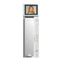
DOORSTATION
BVD 43F(FCPL)-3
SP+ 2
SP- 3
MIC 5
RX 6
GND 1
+E 4
VG 9
VO 10
7
TX 7
8
PRG 8
to commutator
distribution amplifier
/
1
2
3
6
5
4
10
9
DOORSTATION
BVD 43F(FCPL)-3
SP+ 2
SP- 3
MIC 5
RX 6
GND 1
+E 4
VG 9
VO 10
7
TX 7
8
PRG 8
to commutator
distribution amplifier
/
9
9
9
www. - 43 201 - /vizit-group.com BVD 3 F(FCPL) Operating Instruction (revision 5 11) 4 8