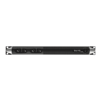
LED Charts
Label Label Type Action Description
2
POWER Pushbutton
keep pressed for
3 seconds
Toggle
system ready/standby mode
3
CALL Pushbutton press
Highlight the amplifier in the
Armonía workspace
4
SOFT
RESET
1
Pushbutton
keep pressed for
3 seconds
Reset network parameters
to factory default
5
HARD
RESET
1
Pushbutton
keep pressed for
3 seconds
Reboot the system
6
CHECK Pushbutton
keep pressed for
3 seconds
Start the self-checking
procedure*
7
CH1
2
Potentiometer
turn
counter-clockwise
Attenuate the output level of
the signal on channel 1
CH2
2
Potentiometer
turn
counter-clockwise
Attenuate the output level of
the signal on channel 2
The push-buttons are disabled when connected to Armonía.
1. Keep pressed both the SOFT RESET button and the HARD RESET button for at least 3 sec-
onds to completely reset the amplifier to its factory default configuration (any preset stored
in the internal memory will be lost and replaced with a flat preset).
2. The potentiometer is in series with the remote level control so it can be used to limit the
output volume regardless to any remote adjustment.
* Press again to resume normal operations
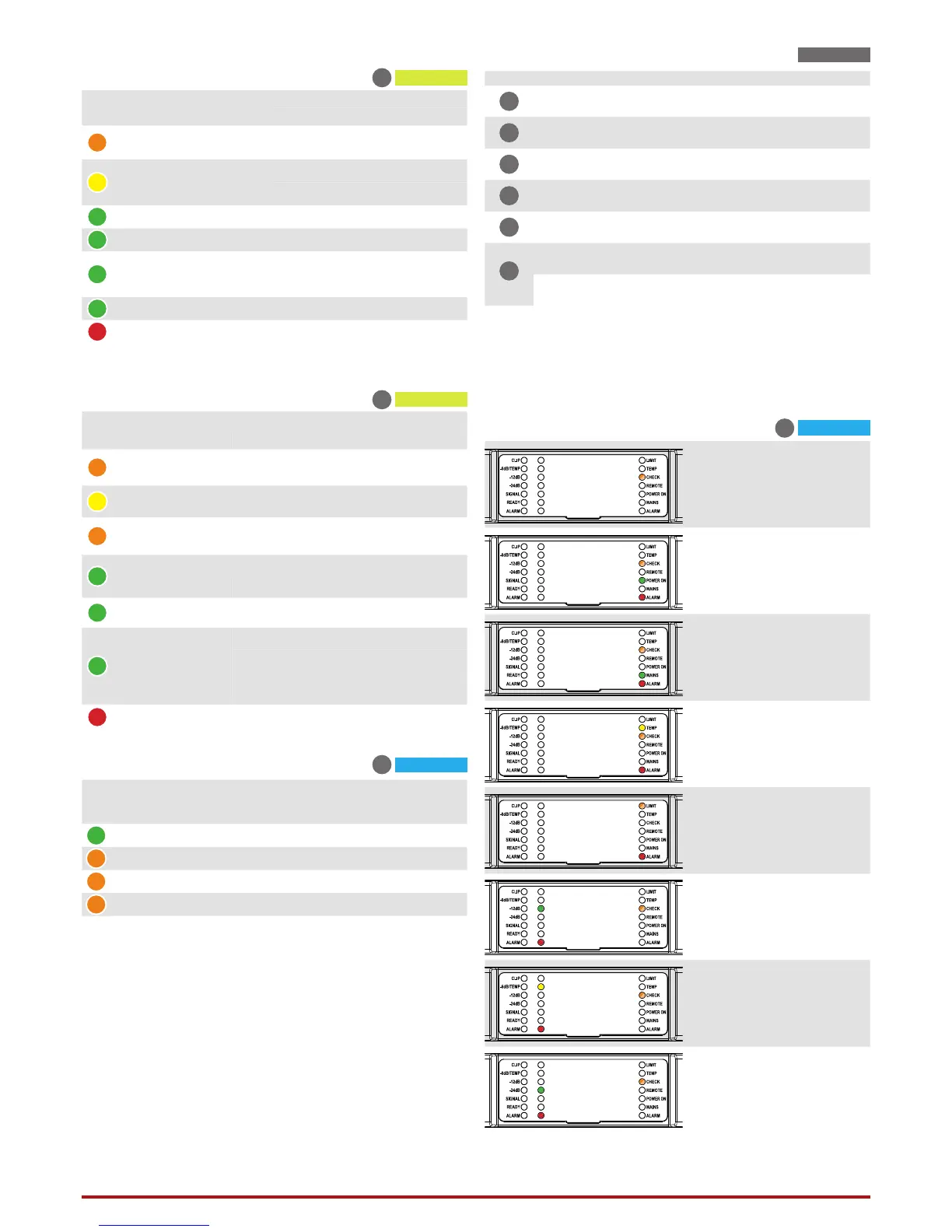
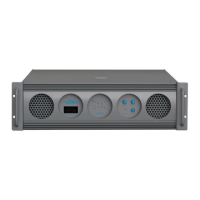
Control Panel
Color Name
Warnings
Lightning Description
ORANGE
LIMIT
FLASHING Breaker Save Enabled
SOLID ON Breaker Save limiting power draw
YELLOW TEMP SOLID ON
Thermal warning
Thermal protection engaged
ORANGE CHECK
SOLID ON System self checking
BLINKING Self check completed
FAST BLINKING Self Check Unavailable
GREEN REMOTE
FLASHING Network connection presence
SOLID ON
Connected to Armonía Pro
Audio
GREEN POWER ON
SOLID ON System ready
OFF System o
GREEN MAINS
SOLID ON
AC mains voltage within the
operating range
OFF Undervoltage
FLASHING Over/Undervoltage Warning
FAST BLINKING Overvoltage
SLOW BLINKING Mains FUSES blown
RED ALARM SOLID ON
PSU fault
1
OR Critical Faults
1
Red LED lights on in case of any kind of PSU fault that prevents normal operating.
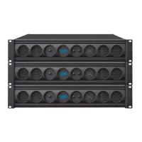
LED Bar, system status
9
Color Signal Metering
Warnings
Lighting Description
ORANGE
Clipping
*DSP+D User Limiter
— —
YELLOW -6dB
SOLID ON
Thermal warning
Thermal protection engaged
FLASHING Auto Standby
GREEN -12dB — —
GREEN -24dB — —
GREEN -60dB
SOLID ON Signal presence
BLINKING Channel muted
GREEN — SOLID ON Channel ready
RED — SOLID ON Channel fault
1
1
Red LED lights on in case of any kind of channel fault that prevents the normal channel
operating; at the same time the rear corresponding GPO toggles the contacts NO into NC
and NC into NO.
LED Bars, signal metering
8
Color Name
Operating mode
Standby Power On
GREEN POWER ON
—
SOLID ON
ORANGE STANDBY SOLID ON
—
ORANGE AUTO STANDBY BLINKING
—
ORANGE ERROR CODE BLINK COUNTER
—
Operating mode LEDs
1
Self Check
6
System OK.
Power supply fault
AC Mains voltage
out of range
(over/under voltage)
PSU temperature
out of range
Fan Error
Channel#
Output Waveform
non-conformity
Channel#
Temperature
out of range
Channel#
Output current measurement
non-conformity
1
1. An 8 Ω dummy load is needed to measure the output current. If the dummy
load is not applied the system reports a fault.