Infinite X
Page 5
Reference Manual
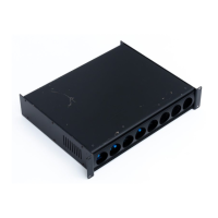
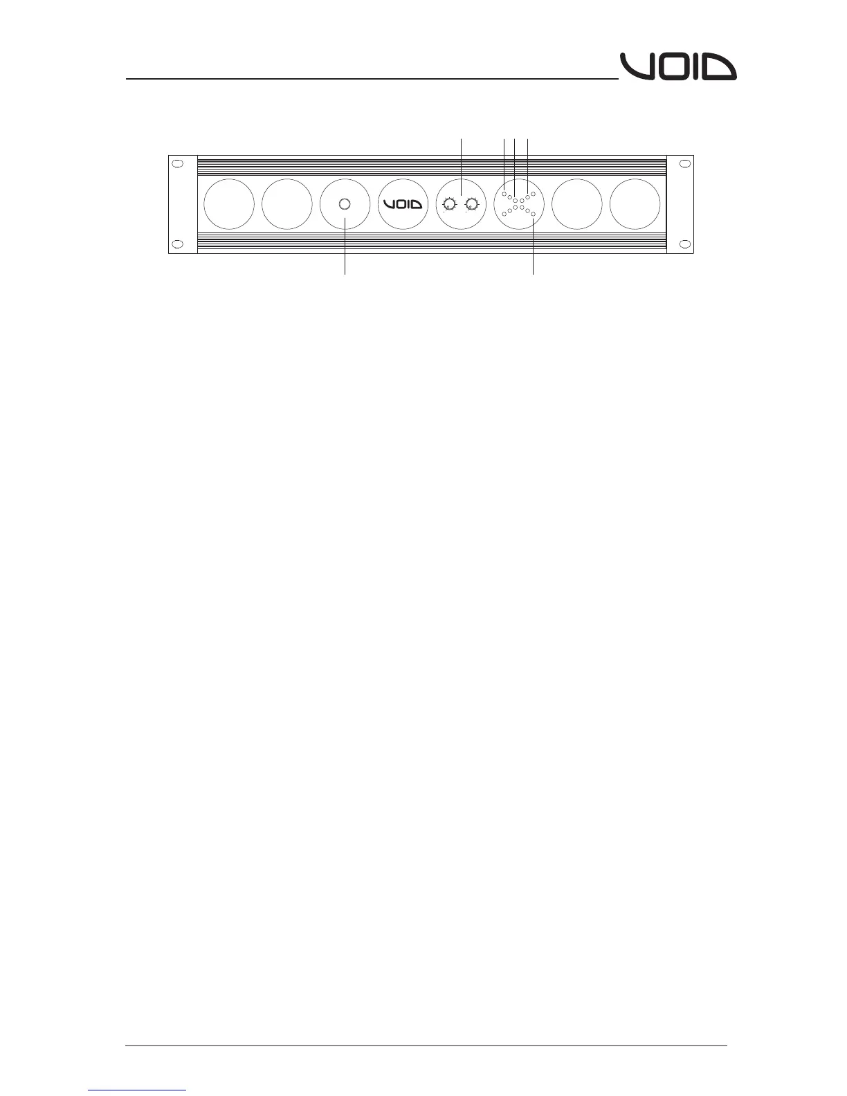
Front Panel
1.Power Switch
Used to turn the amplifier on or off.
2.Level Controls
Used to control CH 1 & 2's output levels.
3.Power LED's
The Power LED's indicate that each channel is active.
4.Signal LED's
When illuminated the LEDs indicate an audio signal is present at the channel's
output.
5.'CEP' LED's (L)
The CEP LED's indicate the Clip Elimination circuit is active. The CEP circuit
works by examining the audio output signal, it then regulates many circuits
within the amplifier to reduce clipping at the output. Note that the CEP circuit
can only prevent a clipped waveform from be generated within the amplifier
itself, it cannot remove a clipped waveform that has been produced from a
component earlier in the chain.
6.Protect LED's (P)
The protect LED's light up when the amplifier detects speaker over excursion,
dangerous subsonic frequencies, DC or thermal overload. Note the protect LED's
also indicate the soft start circuit is active, so will illuminate during power on.
See page 8 for more details about the VSP protection circuit.
1
3
4
5
6
2
Infinite X6
Power
ON -18 -6 0 L P
1
2
0
oo
1
2
0
oo
 Loading...