1
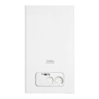
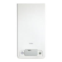
The Mynute VHE comprises a range of high-effi ciency
open-vent boilers with outputs ranging from 12 to 20kW.
These appliances – by design – incorporate premix
com-
bustion and a radial aluminium heat exchanger.
NOTE
This booklet relates specifi cally to the Mynute 15VHE only.
The Mynute 15VHE are produced as room sealed,
category II2H3P appliances, suitable for internal wall
mounting applications only. Each appliance is provided
with a fan powered fl ue outlet with an annular co-axial
combustion air intake that can be rotated – horizontally
– through 360 degrees for various horizontal or vertical
applications; in addition, there is also a facility to re-
confi gure the fl ue outlet from a top outlet to rear outlet.
The Mynute VHE can also be used with the Vokera twin
fl ue system.
These appliances are designed for use with an open-vent
system; consequently they are not intended for use on
sealed or pressurised systems. Please contact the Vokera
technical helpline for advice should you wish to use the
Mynute VHE on a sealed/pressurised system.
Mynute VHE
boiler complies with basic requirements of the
following Directives: Gas directive 2009/142/EC; Yield directive
9
2/42/EEC;
- Electromagnetic compatibility directive 2004/108/EC;
- Low-voltage directive 2006/95/EC;
- Directive 2009/125/EC Ecodesign for energy-using ap-
pliances;
- Directive 2010/30/EU Indication by labelling of the con-
sumption of energy by energy-related products;
- Delegated Regulation (EU) No. 811/2013;
- Delegated Regulation (EU) No. 813/2013;
When the product reaches the end of its life it should
not be disposed of as solid urban waste but should be
brought to a separated waste collection facility.
This booklet is an integral part of the appliance. It is
therefore necessary to ensure that the booklet is handed
to the person responsible for the property in which the
appliance is located/installed. A replacement copy can
be obtained from Vokera customer services.
All installers are asked to follow the Benchmark Scheme
by adhering to the Code of Practise, which can be obtai-
ned from www.centralheating.co.uk.
INTRODUCTION
Fig. 1
G
F
R
General layout (fi g. 1)
1 Gas valve
2 Injector
3 Fan assembly
4 Return sensor
5 Condensate level sensor
6 Main heat exchanger
7 Spark Electrode
8 High limit thermostat
9 Limit thermostat
10 Internal fl ue gas analysis test point
11 External fl ue gas analysis test point
12 Flue outlet & air intake
13 Top AAV
14 Drain pipe
15 Flow sensor
16 Sensing Electrode
17 Ignition transformer
18 Condense trap
19 Condensing drain
R Heating return connection
F Heating fl ow connection
G Gas connection
The Mynute VHE is approved for use with C13 & C33
type fl ue applications.
 Loading...