Do you have a question about the Voltronic Power Axpert VM III-5000 and is the answer not in the manual?
Manual overview and structure, detailing its five main parts.
Explains the topology of the Hybrid Inverter (VM III).
Details different inverter models and their important parameters.
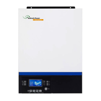
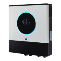
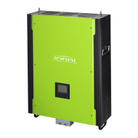
Identifies key components of the Axpert VMIII inverter.
Guidance on initial steps when the inverter is faulty.
Notes for inspecting for physical damage during troubleshooting.
Troubleshooting steps for no power or display issues.
Diagnosis and repair for '09 fault' (Bus soft start failure).
Troubleshooting steps for battery detection issues.
Procedures to confirm repair results after component replacement.
Details on checking fuses and capacitors on the main board.
Lists DC/DC MOSFETs and their specifications for checking.
Checking driver transistors and control ICs on the battery side.
Details on checking components on the bus side of the main board.
Checking components of the buck circuit on the main board.
Instructions for checking the INV full bridge on the main board.
Procedures for checking BATT and Main Power SPS components.
Procedures for checking AC SPS components.
Steps to check the bus soft start circuit for specific faults.
Checking boost IGBTs and diodes on the MPPT board.
Instructions for removing the top and rear panels.
Steps to disconnect various cables from the unit.
Steps to remove the main board from the chassis.
Illustrates the overall wiring connections of the inverter.
| Model | Axpert VM III-5000 |
|---|---|
| Waveform | Pure sine wave |
| Cooling Fan | Yes |
| Storage Temperature | -15°C to 60°C |
| AC Input Voltage | 230 VAC |
| DC Input Voltage | 48V |
| AC Output Voltage | 230VAC |
| Output Frequency | 50/60Hz |
| Input Voltage Range | 90-280VAC |
| Battery Voltage | 48V |
| Battery Type | Lithium |
| Transfer Time | 10ms |
| Communication Port | RS232, USB |
| Protections | Overload, Over Temperature, Short Circuit |
| Operating Temperature | 0°C to 40°C |
| Humidity | 5% to 95% (Non-condensing) |