This document serves as a service manual for the Axpert MKS-4000/KS-5000 series of charger/inverters from Voltronic Power. It is primarily intended for service personnel to perform basic maintenance and repair. The manual assumes prior knowledge of the device's basic operation, as outlined in the user manual, and emphasizes the importance of reading and understanding the user manual before utilizing this service guide.
The manual is structured into eight sections, each addressing a specific aspect of the device:
- General Information: Provides an overview of the service manual itself, outlining its purpose and scope.
- Functional Block: Details the major functional blocks of the Inverter/Charger, presenting a high-level architectural view.
- Working Principle of the Major Functional Block: Explains the operational principles of each significant functional block within the device.
- Function Explanations for Each PCB: Offers detailed descriptions of all Printed Circuit Boards (PCBs) present in the Inverter/Charger.
- Interface: Covers the LCD interface, including its display elements and settings.
- Troubleshooting: Guides users through the process of identifying and resolving issues.
- Test Step: Provides instructions on how to test the Inverter/Charger after repairs.
- Electric Specifications: Presents the fundamental electrical specifications of the Inverter/Charger.
Function Description:
The Axpert MKS 4KVA-5KVA series employs a double conversion topology, integrating several key functional blocks to manage power flow and conversion. These blocks include:
- MPPT Solar Charge Controller: This component, utilizing an interleaved buck converter, manages the charging of batteries from a solar power source. It incorporates an NTC sensor for temperature monitoring.
- DC/DC Converter Charger: This full-bridge converter facilitates bidirectional power transfer between the battery and the internal DC bus. It's designed to either discharge power from the battery to the bus or charge the battery from the bus, depending on voltage differentials. It also includes thermal switch protection and an NTC sensor.
- DC/AC Inverter AC/DC Rectifier: This block handles the conversion between DC and AC power. It functions as an inverter to supply AC loads from DC sources (like batteries) and as a rectifier to convert incoming AC power (from grid or generator) into DC for charging or internal use. It also features an NTC sensor.
- Switch Power Supply (SPS): This unit provides the necessary DC power for the overall operation of the Inverter/Charger. Its input can be either the battery voltage or the AC charger output voltage. It's a fly-back DC-DC converter capable of generating multiple output voltages (+12V, -12V, +15V, +5V, HFPW+).
- Inverter (Full bridge): This circuit, active in both battery and line modes, is responsible for generating the AC output. In line mode, it can convert grid power to the DC bus for charging. It uses a full-bridge circuitry with photo-couplers to drive MOSFETs and IGBTs, generating a high-frequency PWM output that is then filtered by an LC circuit to minimize harmonic distortion.
- Buck Converter: This circuit is specifically active when the unit is charging the battery from an AC line source. It acts as a filter inductor when the battery is discharging.
The device's control and communication are managed by several PCBs:
- Main board: Houses the SPS, DC-DC converter, and inverter. It contains numerous semiconductors and components prone to failure, requiring careful attention during system abnormalities.
- Cntl board: Integrates AD sampling, MCU control, and a communication module, orchestrating the orderly operation of other modules.
- SCC board (Solar Current Control): Based on a PW control mode, this board manages battery charging from solar sources, capable of delivering up to 50A if sufficient solar energy is available.
- COMM board: Provides a communication port for PC connectivity, enabling interaction with corresponding software via an RS-232 port.
- LED board: Features three indicators and four functional keys for user interaction and status display.
- MPPT board: Comprises the SPS, BUCK converter, and MCU control, integrating the MOSFET driver board and SPS driver board. Like the main board, it contains many semiconductors and failure-prone components, necessitating careful observation during system malfunctions.
Usage Features:
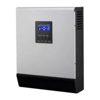
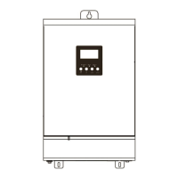
The inverter/charger features an intuitive operation and display panel on its front, which includes:
- Three LED indicators: Provide quick visual cues about the device's status.
- AC/INV (Green): Solid On indicates output available in bypass mode; Flashing indicates output powered by battery in inverter mode.
- CHG (Green): Solid On indicates battery is fully charged; Flashing indicates battery is charging.
- FAULT (Red): Solid On indicates a fault mode; Flashing indicates a warning mode.
- Four function keys (ESC, UP, DOWN, ENTER): Allow users to navigate menus, adjust settings, and confirm selections.
- LCD display: Presents detailed operating status and input/output power information, including:
- Input Source Information: Icons for AC and PV input, and numerical displays for input voltage, frequency, PV voltage, battery voltage, and charger current.
- Configuration Program and Fault Information: Displays setting programs, warning codes (flashing), and fault codes (lighting).
- Output Information: Shows output voltage, frequency, load percentage, load in VA, and load in Watt.
- Battery Information: Indicates battery level (0-24%, 25-49%, 50-74%, 75-100%) in battery mode and charging status in line mode. It also provides detailed battery charging status (Battery voltage, Constant Current mode/Constant Voltage mode, Floating mode) and battery capacity based on load percentage.
- Load Information: Indicates overload status and load level (0-24%, 25-50%, 50-74%, 75-100%).
- Mode Operation Information: Icons to indicate connection to mains, PV panel, load supplied by utility power, utility charger circuit working, and DC/AC inverter circuit working.
- Mute Operation: An icon indicates if the unit alarm is disabled.
Maintenance Features:
The manual provides comprehensive troubleshooting guidance, emphasizing a structured approach to problem-solving:
- Check System Status: Observe LED and LCD displays, and listen for buzzer sounds.
- Observe Failure Board: Visually inspect the relevant PCB for obvious issues.
- Static Checking: Perform static checks on components.
- Replace Failure Components: Replace any identified faulty components.
- Power Up Checking: Verify functionality after component replacement.
- Test After Repair: Conduct thorough testing to ensure the unit operates correctly.
A detailed Fault Reference Code table lists various fault events (e.g., Fan is locked, Over temperature, Battery voltage too high/low, Output short circuited, Overload, Bus voltage too high, Main relay failed, Over current inverter, Self-test failed, Over DC voltage on output of inverter, Battery connection is open, Current sensor failed) along with their corresponding fault codes displayed on the LCD.
A Warning Indicator table outlines warning events (e.g., Fan is locked, Battery is over charged, Low battery, Overload, Power limitation), their audible alarms (e.g., beep patterns), and icon flashing patterns.
The Troubleshooting According to Fault Indication section provides practical solutions for common problems:
- Unit shuts down automatically during startup: Suggests recharging or replacing the battery if voltage is too low.
- No response after power on: Advises checking battery connections, recharging, or replacing the battery, and verifying battery polarity.
- Mains exist but the unit works in battery mode: Recommends checking for tripped AC breakers, proper AC wiring, and the quality of AC power (shore or generator), including wire thickness and length, and input voltage range settings.
- Internal relay switches on and off repeatedly: Points to a disconnected battery, overload errors, internal converter over-temperature, or battery overcharge/high voltage. Solutions include checking battery wires, reducing load, inspecting airflow, and returning to a repair center if necessary.
- Buzzer beeps continuously and red LED is on: Indicates fan fault, abnormal inverter output voltage, or internal component failures. Solutions involve replacing the fan, reducing connected load, restarting the inverter, and returning to a repair center for persistent issues.
Finally, a Quick Start section provides a table of checked components (Fuses, MOSFETs, Diodes, Drivers, IGBTs, Resistors) with their instruction functions, reference values, and indications of failed status (short or open), aiding in rapid diagnosis. It emphasizes the critical step of checking capacitor voltages to ensure they are below safety levels before any inspection.
This comprehensive service manual aims to equip service personnel with the necessary information and procedures to effectively maintain and repair the Axpert MKS-4000/KS-5000 series inverter/chargers, ensuring their reliable operation.