47
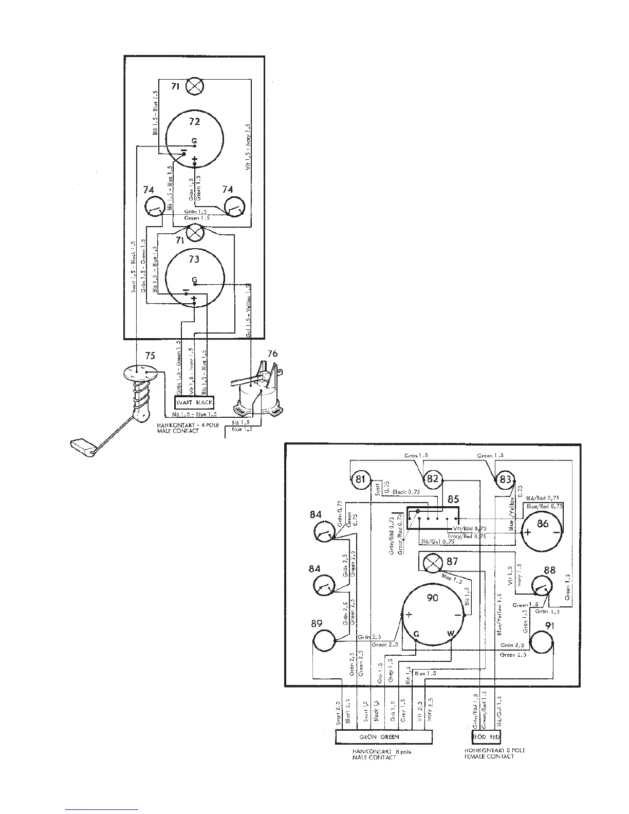
Fig. K5. Wiring diagram. Panel with fuel gauge and rudder
indicator.
71. Instrument lighting
72. Fuel gauge
73. Rudder indicator
74. Extra switches (max. 5 A per switch)
75. Sender, fuel gauge
76. Sender, rudder indicator
(The free, blue 1.5 cable should be connected to 104 on the
engine terminal box)
Fig. K6. Wiring diagram
Flying Bridge instrument panel
81. Battery charging warning lamp
82. Oil pressure warning lamp – engine
83. Coolant temperature warning lamp
84. Extra switches (max. 5 A per switch)
85. Alarm separator
86. Siren
87. Instrument lighting
88. Switch, instrument lighting
89. Stop button
90. Rev counter
91. Starter button