6
Instruments and controls
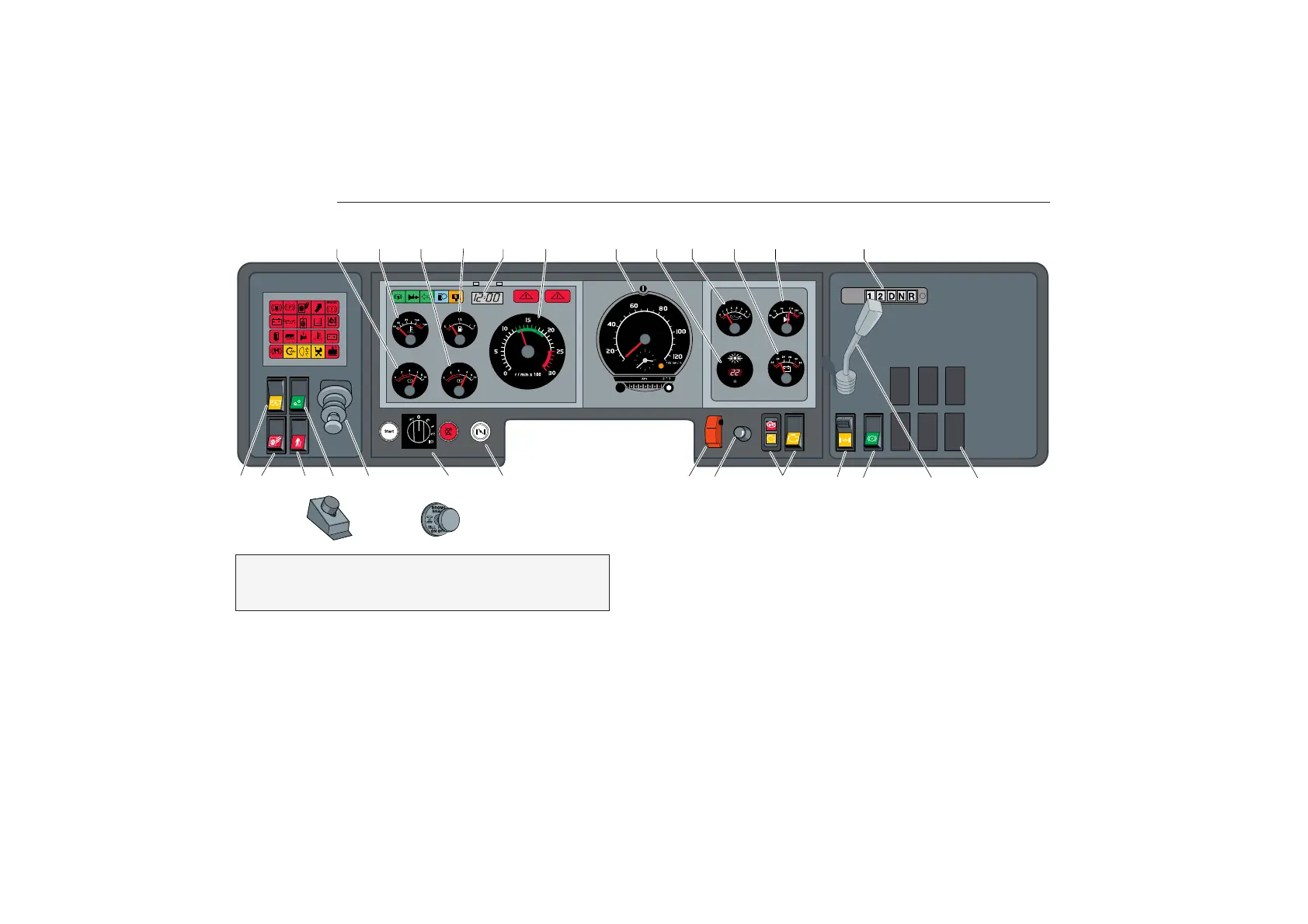
Dashboard
The illustrations show the most common switch loca-
tions, but there can be variations. Symbols and explana-
tions of functions are, however, always accurate.
6. Engine speed .......................................................... 16
7. Tachograph/speedometer ...................................... 20
8. Temperature, ext./int. .............................................. 31
8. alt. compressed air (articulated bus) ...................... 24
9. Lubricant pressure, engine ..................................... 17
10. Voltmeter ................................................................. 15
11. Oil temperature, automatic gearbox ....................... 19
or
11. Turbo pressure ........................................................ 16
12. Gear selector, automatic gearbox .......................... 42
123456 7891011 12
13 14 15 16 17 20 21 22 23 24 25 26 27 28
18 19
page
1. Compressed air, front circuit .................................... 24
2. Coolant temperature ............................................... 18
3. Compressed air, rear circuit ................................... 24
4. Fuel level ................................................................. 16
5. Clock and tripmeter ................................................. 31
Left hand drive
bus