Do you have a question about the Von Duprin 98/9927 and is the answer not in the manual?
| Type | Exit Device |
|---|---|
| Model | 98/9927 |
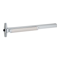
| Device Type | Rim Exit Device |
| Series | 98 |
| Fasteners | Screws |
| Handing | Universal |
| Mounting | Surface Mounted |
Establish the horizontal center line and assemble the device template onto the door.
Position the template correctly and mark the vertical centerline, considering different backsets.
Align top and bottom templates with centerlines and prepare the door according to the preparation chart.
Determine if the NL drive screw needs removal for specific trim operations.
Install the tailpiece guide and adjust the tailpiece for cylinders.
Attach the trim and secure the device's center case to the door.
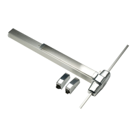
Mark and prepare two mounting holes for the end cap bracket.
Secure the end cap bracket and the end cap to the device.
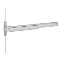
Install the top latch mechanism and connect the top rod.
Install the appropriate strike plate for the top of the door.
Adjust the top rod by screwing it in or out to ensure proper latch operation.
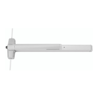
Install the bottom strike, latch mechanism, and connect the bottom rod.
Adjust the bottom rod with the door open to ensure correct deadlatching.
Install the rod guides at the midpoint of each rod and attach the covers.