Do you have a question about the Von Duprin M996L Series and is the answer not in the manual?
Instructions for switching between Fail Safe (FS) and Fail Secure (FSE) modes.
Verify NL drive screw position for rim/vertical exit device applications.
Confirm NL screw setting for mortise device applications.
Drill and deburr 3/8" diameter hole for wiring on exit device side.
Mark, drill, and deburr 5/8" hole for wiring access.
| Series | M996L |
|---|---|
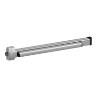
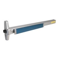
| Device Type | Exit Device |
| Fasteners | Included |
| Dogging | Hex key dogging standard |
| Strike Adjustability | Yes |
| Type | Rim |
| Material | Steel |
| Door Type | Metal or wood |
| Door Width | 36" to 48" |
| Door Height | Up to 10 feet |
| UL Listing | UL 305 |
| ANSI | A156.3 |
| Compliance | ADA Compliant |
| Mounting | Surface |