Do you have a question about the Vonyx VXA Series and is the answer not in the manual?
Switches the amplifier on and off. Always adjust the volume to minimum before switching on.
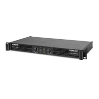
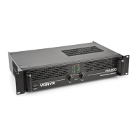
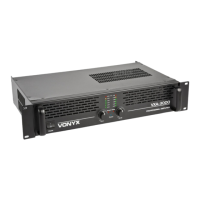
Front to rear forced airflow for amplifier cooling.
Adjusts the volume level of both channels. Turn left if clip indicators light up.
Three orange LEDs indicating the amplifier's output signal levels.
LEDs light up at max power. Continual lighting requires volume adjustment to prevent damage.
Indicates when the amplifier enters protect mode due to potential damage or faults.
A clear blue indicator that lights up when the amplifier is turned on.
Two 6.3mm jack female input connectors for connecting a signal source like a mixer.
Two RCA input connectors for connecting a signal source like a mixer.
Selects between stereo mode (standard left/right) and bridge mode (double power).
Separates circuit and chassis grounds to resolve earth loop hum problems.
Outputs for connecting speakers, max load 4 Ohm per channel in stereo mode.
NL4 speaker outputs. Max load 4 Ohm per channel in stereo mode.
Output jacks for speakers. Max load 4 Ohm stereo, 8 Ohm bridge.
Secures the amplifier against defects. Replace only with the same type and value.
Guide to connecting speakers using NL4 plugs or bare wire, including setup modes.
Sets the amplifier to standard left/right stereo mode with independent channels.
Combines channels for double power. Connect signal to left input, use left volume control.
Connects the amplifier to the AC mains power supply, ensuring correct voltage matching.
| Power Output | Check specific model within VXA Series |
|---|---|
| Frequency Response | Check specific model within VXA Series |
| Input Sensitivity | Check specific model within VXA Series |
| Signal to Noise Ratio | Check specific model within VXA Series |
| Total Harmonic Distortion | Check specific model within VXA Series |
| Input Connections | Check specific model within VXA Series |
| Output Connections | Check specific model within VXA Series |
| Cooling | Check specific model within VXA Series |
| Impedance | Check specific model within VXA Series |
| Input Impedance | Check specific model within VXA Series |
| Power Supply | Check specific model within VXA Series |
| Damping Factor | Check specific model within VXA Series |
| Dimensions | Check specific model within VXA Series |
| Weight | Check specific model within VXA Series |