Contents [ hide
1 Wire Harness Colors and Functions
1.1 Power Connector (8-pin High-Current Connector)
1.2 Alarm / Notification Connector (4-pin connector) See page 33 for the full system
diagram.
1.3 Input / Output Connector (22-pin connector) See page 33 for the full system diagram.
2 External Components
2.1 Shock Sensor
2.2 RF Antenna / LED / Programming Port
2.3 Data Bus Interface (DBI) Port
2.4 Telematics Interface Port
3 Setup Options
3.1 Bank 1: Add / Remove Remote Controls
3.2 Security Control (Bank 2)
3.3 Remote Start Control (Bank 3)
3.4 Negative Output Control (NOC)
4 Auxiliary Output Control (AUX Control)
4.1 Programmable Input Control (PIC Control)
5 System Operation
5.1 Manual Transmission Mode (Ready Mode)
5.2 Remote Control Operation
6 Quick Reference
6.1 Setup Options
6.1.1 Programming Mode Entry and Exit Procedure
6.1.2 Feature Bank Options
6.2 Programming & Diagnostics
6.2.1 Data Port Protocol Selection
6.2.2 Tach Function
6.2.3 Dome Light Delay
6.2.4 Turbo Timer
6.2.5 Silent Arm and Disarm
6.2.6 Adjusting the Shock Sensor
6.2.7 Troubleshooting Trigger Zones
6.2.8 Troubleshooting Remote Start
6.2.9 Alarm Override Procedures
6.3 Wiring Diagrams
6.3.1 Door Lock Connections
6.3.2 Starter Kill / Anti-Grind Relay Connections
6.3.3 Full System Connections
6.4 File Downloads
6.5 References
6.6 Related Manuals
Wire Harness Colors and Functions
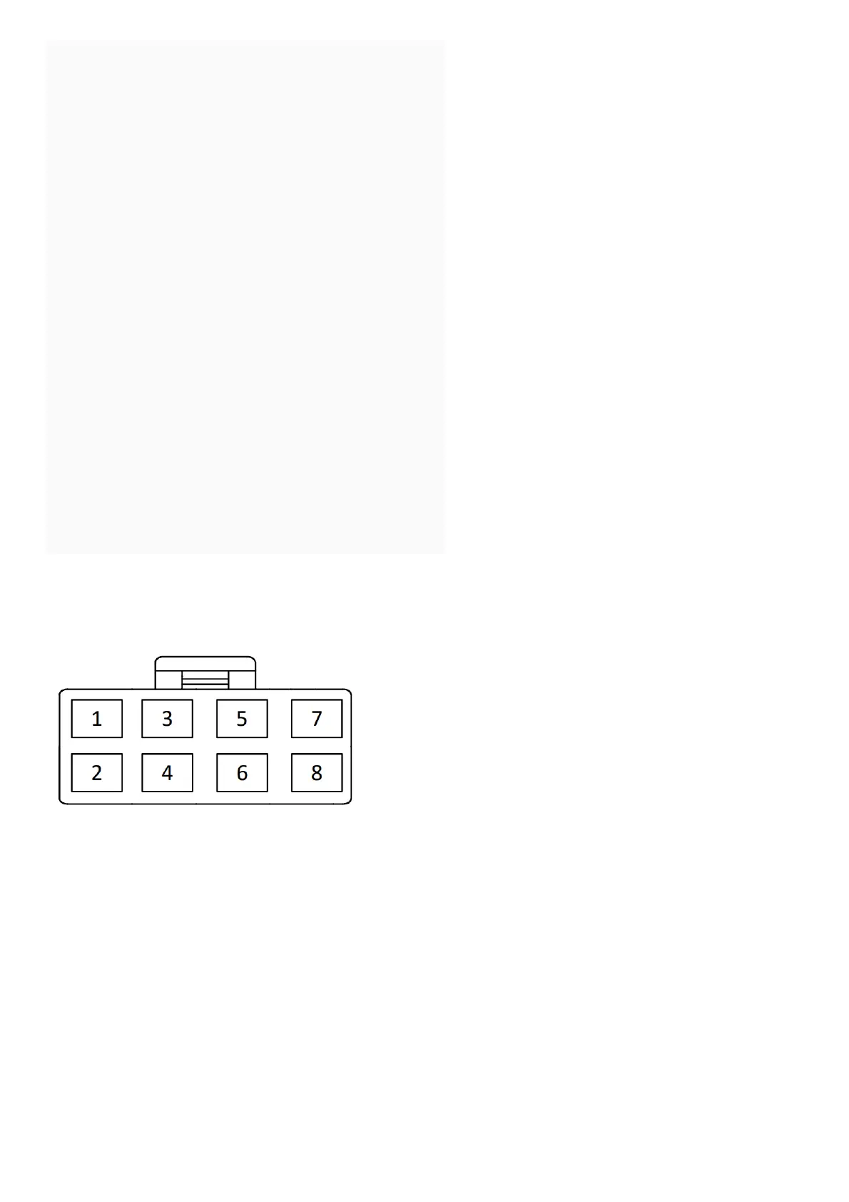
Power Connector (8-pin High-Current Connector)
See page 33 for the full system diagram.
These wires are listed in order of their placement in the harness connector.
1. RED/BLACK – Ignition 3, Flex Relay Input (Internal Relay Pin 87)
The RED/BLACK wire is used to supply the Pin 2 – PINK Flex Relay Output. This wire can be connected to 12-Volt (+) or Ground (-). Please check vehicle requirements for correct
polarity.
Note: Before making this connection, remove all module fuses until the system is completely connected.
2. PINK – Ignition 3 Flex Relay Output (Internal Relay Pin 30)
At its default setting, the PINK wire supplies 12-Volt (+) or Ground (-) to the vehicle’s secondary ignition wire during remote start. The polarity of this output is provided by the Pin 1,
RED/BLACK Input.
Verification: If present, the secondary ignition wire registers 12-Volt (+) or Ground (-) when the vehicle is in ignition mode AND during engine crank.
Note: This wire can be programmed to perform a different function by changing its options. Refer to Bank 3, Feature 8 on page 13.
3. YELLOW – Starter Output for Remote Start (+)
The YELLOW wire supplies 12-Volt (+) to the vehicle’s starter wire when remote start is enabled and turns off once the vehicle is started.
Verification: This starter wire registers 12-Volt (+) during engine crank.
Note: If installing a starter kill relay in addition to remote start, connect the YELLOW wire to the MOTOR SIDE of the cut starter wire. Refer to the Start Kill diagram on page 32.
4. GREEN – Ignition 2 Output (+)
At its default setting, the GREEN wire supplies 12-Volt (+) to the vehicle’s secondary ignition wire during remote start. Verification: If present, the secondary ignition wire registers 12-
Volt (+) when the vehicle is in ignition mode AND during engine crank.
Note: This wire can be programmed to perform a different function by changing its options. Refer to Bank 3, Feature 7on page 13.
5. RED – 12-Volt Input (+)
The RED wire connects to the vehicle’s primary 12-Volt (+) wire to power the system.
Verification: The power wire registers 12-Volt (+) at all times.
Note: Before making this connection, remove all module fuses until the system is completely connected.
6. RED/WHITE – 12-Volt Input (+)
The RED/WHITE wire connects to the vehicle’s secondary 12-Volt (+) wire to power the remote start function.
Verification: The power wire registers 12-Volt (+) at all times.
Note: Before making this connection, remove all module fuses until the system is completely connected.
7. PURPLE – Accessory Output (+)
At its default setting, the Purple wire supplies 12-Volt (+) to the vehicle’s accessory wire to power vehicle accessories during remote start.