Verification: The accessory wire registers 12-Volt (+) when the vehicle is running or in accessory mode, but not during engine crank or if the vehicle is off.
Note: This wire can be programmed to perform a different function by changing its options. Refer to Bank 3, Feature 9on page 13.
8. BLUE – Ignition 1 Input / Output (+)
The BLUE wire supplies 12-Volt (+) to the vehicle’s primary ignition wire during remote start. This wire is also used to sense vehicle ignition for the Programming Functions Verification:
The primary ignition wire registers 12-Volt (+) when the vehicle is in ignition mode AND during engine crank.
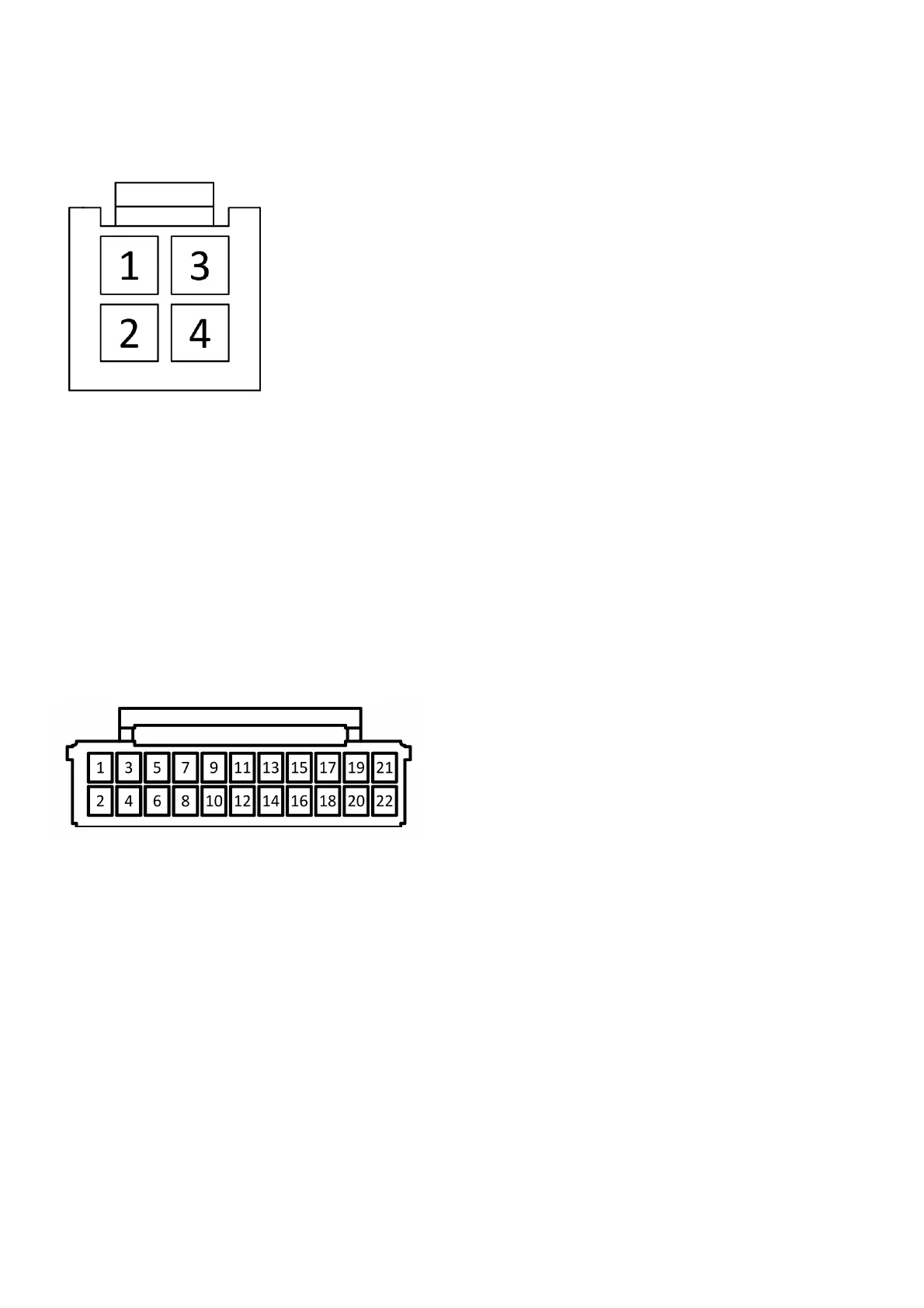
Alarm / Notification Connector (4-pin connector) See page 33 for the full system diagram.
These wires are listed in order of their placement in the harness connector.
1. WHITE – Parking Light Relay Output (Internal Relay Pin 30)
At its default setting, the WHITE wire supplies 12-Volt (+) or Ground (-) to the vehicle’s park light wire based on the connection of the relay input (WHITE/RED wire).
Verification: The vehicle parking light wire registers 12-Volt (+) or Ground (-) when the park lights are turned on. Note: This wire can be programmed to perform the Trunk Release
Output function by changing its options. Refer to Bank 2, Feature 14 on page 9.
2. WHITE/RED – Parking Light Relay Input (Internal Relay Pin 87)
The WHITE/RED connects to vehicle 12-Volt (+) or Ground (-) to supply the relay output (WHITE wire).
Verification for default setting:
• If the vehicle parking light wire registers 12-Volt (+) when the park lights are on, connect the WHITE/RED wire to a constant 12-Volt (+) vehicle wire.
• If the vehicle parking light wire registers Ground (-) when the park lights are on, connect the WHITE/RED wire to a reliable vehicle ground
Note: This wire can be programmed to perform the Trunk Release Output function by changing its options. Refer to Bank 2, Feature 14 on page 9.
3. WHITE/BLACK – Siren Output (+)
The WHITE/BLACK wire supplies 12-Volt (+) to power the siren. After mounting the siren, connect its BLACK wire to a reliable ground source, and connect the WHITE/BLACK wire to
the siren’s RED wire.
4. BLACK – Ground Input (-)
The BLACK wire connects to a reliable vehicle ground (-) source to power the system.
Verification: The vehicle ground (-) source wire registers ground (-) at all times.
Note: Before making this connection, remove all module fuses until the system is completely connected.
Input / Output Connector (22-pin connector) See page 33 for the full system diagram.
These wires are listed in order of their placement in the harness connector.
1. ORANGE – Starter Kill Output (-)
The ORANGE wire supplies Ground (-) when the alarm is armed and when the remote start is ON.
2. LIGHT GREEN – Trunk / Hatch Input (-) (PIC1)
The LIGHT GREEN wire connects a device or switch that, when triggered, supplies a Ground (-) output. If the system is armed, this input will trigger the alarm.
Note: This wire is programmable. Refer to PIC Programming on page 20.
3. GRAY/BLACK – Hood Input (-) (PIC2)
The GRAY/BLACK wire connects to the vehicle’s hood switch or an installed switch that registers Ground (-) when triggered.
Note: This wire is programmable. Refer to PIC Programming on page 20.
Verification: The vehicle hood switch wire registers Ground (-) when the hood is opened.
4. GREEN/ORANGE – Tach Input
The GREEN/ORANGE wire connects to the vehicle’s tach wire at the negative side of the ignition coil or fuel injector to control the engine crank during remote start.
Verification:
• Using a voltmeter set to AC volts, connect the voltmeter’s positive lead to a constant vehicle 12-Volts (+) source and the negative lead to the wire to be
• Start the engine and have a partner slowly press the gas pedal while the transmission is in If the voltage increases as the RPM increases, this is the proper tach wire.
5. LIGHT BLUE – Remote Start Status Output (-) (NOC 1)
The LIGHT BLUE wire supplies Ground (-) as soon as the remote starter is activated and remains active until (4) seconds after remote start run time has ended. This wire is most
commonly used to activate data integration modules.
Note: This wire is programmable. Refer to NOC Programming on page 11.
6. PURPLE/BROWN – Door Trigger Input (-/+)
The PURPLE/BROWN wire connects to the vehicle’s door trigger wire. This wire will detect 12-Volt (+) or Ground (-) input. Verification: The vehicle door trigger wire registers 12-Volt
(+) or Ground (-) when a door is opened and opposite when closed.
Note: Programming is required if the door trigger wire registers 12-Volt (+). Refer to Feature Programming on page 9.
7. GREEN/WHITE – Dome Light Output (-) (NOC 2)
The GREEN/WHITE wire supplies Ground (-) when Unlock is activated from the Remote Control. This output will automatically turn off after 30 seconds.
Note: This wire is programmable. Refer to NOC Programming on page 17.
8. GREEN/YELLOW – Diesel Glow Plug Input (+) (PIC3)
The GREEN/YELLOW wire connect to the vehicle’s Diesel Glow Plug detection wire.
Verification: This wire will register as 12-Volt (+) while the Diesel Wait to Start Light is illuminated.
Note: This wire is programmable. Refer to PIC Programming on page 20.
9. BLACK/YELLOW – Pulse During Crank Output (-) (NOC 3)
At its default setting, the BLACK/YELLOW wire supplies a Ground (-) pulse when the engine cranks during remote start.
Note: This wire is programmable. Refer to NOC Programming on page 17.


 To Next Page