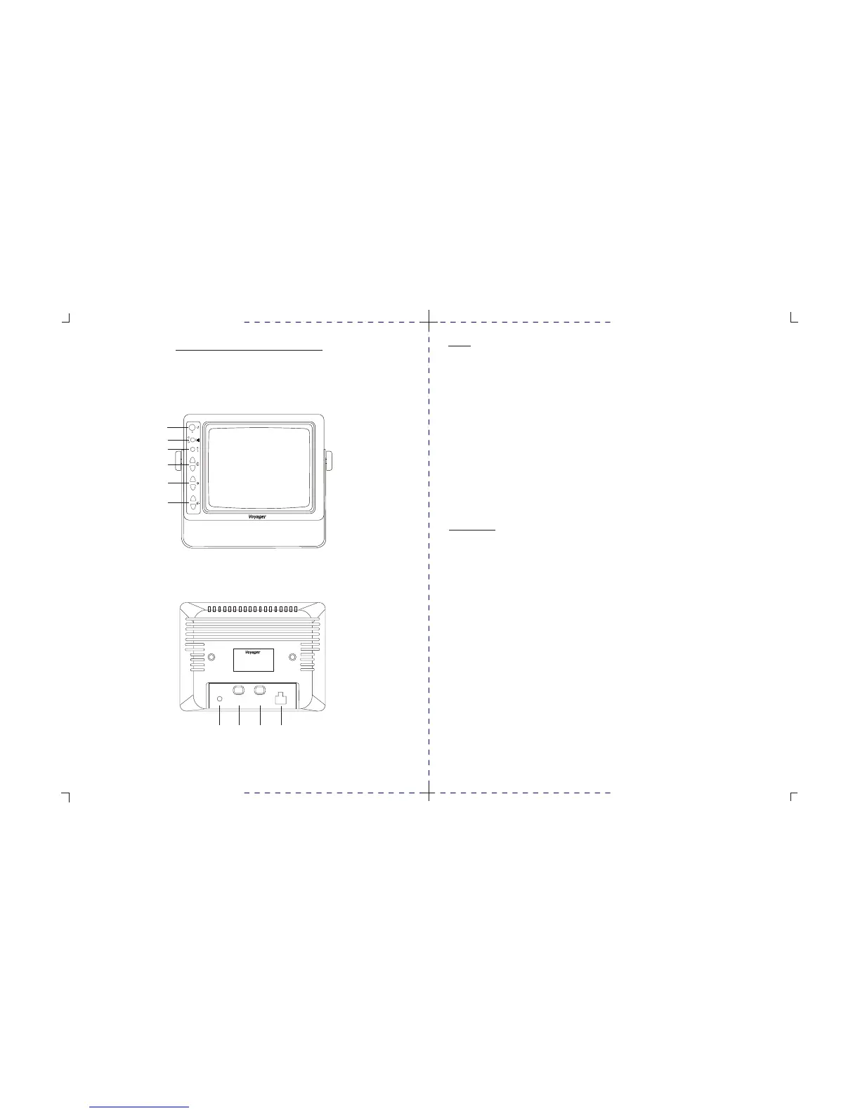
Monitor
1. Power switch
STD. BY - Monitor operates when vehicle transmission is switched into “ REVERSE ”.
ON - Monitor and system operate when ignition switch is “ ON ”.
2. Input switch
“ A ” used mainly for rear mounted camera or as specified by the installer.
“ B ” used mainly for side or mirror mounted camera or as specified by the installer.
3. Day / Night switch
Pre-set brightness and contrast levels optimized for day and night operation.
4. Contrast
Variable control or contrast. Should be adjusted if the “ DAY / NIGHT ” switch does not achieve the most
desirable picture.
5. Brightness
Variable control of brightness. Should be adjusted if the “ DAY / NIGHT ” switch does not achieve the most
desirable picture.
6. Volume
Variable control of internal speaker and external speaker volume.
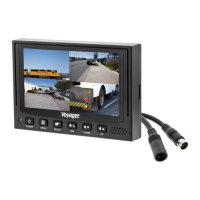
Rear of Monitor
1. Power connection : Pin 1 not used
Pin 2 Ground - black wire
Pin 3 Reverse circuit - blue wire
Pin 4 not used
Pin 5 battery backup - yellow wire
Pin 6 + 12VDC ignition - red wire
2. Camera A input connection to camera extension cable.
3. Camera B input connection to additional camera extension cable.
4. External speaker connection center pin is positive audio output, used to disable the internal
speaker and remotely mount a speaker for driver convenience.
MONITOR OPERATING CONTROLS AND CONNECTIONS
À
Á
ÂÃ
* MONITOR BACK VIEW
* MONITOR FRONT VIEW
MODEL : AOM-78
POWER SOURCE : D C11V~30V
OUTPUT POWER : MAX 22W
MADE IN MALAYSIA
CA1
CA2
POWER
EXT
SPKR
À
Á
Â
Ã
Ä
Å
POWER
INPUT
DAY/NIGHT
–
+
–
+
–
+
A
B
CONTROLS AND OPERATION
3 4