2 Component Removal and Installation
18
Meritor WABCO Maintenance Manual 34 (Revised 03-16)
6. Install new O-ring on cover.
7. Apply a thin layer of grease to the valve bore and the O-rings.
8. Install the new piston with flat side toward dryer.
9. Install the new spring, cover and snap ring to hold the
components in place.
10. Install the plug.
11. Replace the desiccant cartridge.
System Saver 1200 Plus Turbo Cut-Off Valve
Assembly
1. Remove the snap ring. Figure 2.9.
Figure 2.9
2. Remove the cover.
3. Remove the piston and sleeve.
4. Clean and inspect the valve bore. If the bore is damaged so
that a tight seal cannot be maintained, replace the air dryer.
5. Apply a thin layer of grease to the valve bore and the O-rings.
6. Install new O-rings on the piston and sleeve.
7. Press the piston into the sleeve.
8. Press the piston-sleeve assembly into the air dryer.
9. Install the cover and snap ring.
10. Replace the desiccant cartridge using the detailed instructions
provided earlier in this section.
System Saver 1200 Plus Governor
Function— The governor controls the cut-in and cut-out pressure
of the compressor through signal lines from the system reservoir as
well as the compressor head controlling onload and offload.
Use only the Meritor WABCO governor specified for use with the
System Saver 1200 Plus air dryer.
NOTE: Some models have O-rings instead of a gasket.
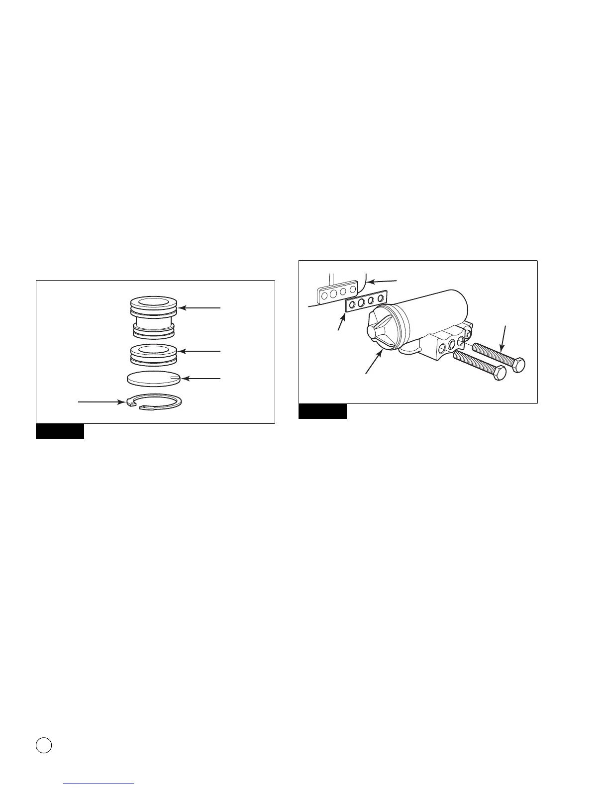
1. Remove the mounting bolts, governor and gasket or O-rings.
Discard the gasket or O-rings. Figure 2.10.
Figure 2.10
2. Place the governor and a new gasket or O-rings into position
on the air dryer.
3. Install the mounting bolts and tighten to 14.75 ft-lb (20 N폷m).
@
Regeneration Valve Assembly
The regeneration valve assembly kit contains two different
diaphragms to service the regeneration valve assembly for System
Saver 1200 or 1800 air dryers. Use the correct diaphragm for the
style of regeneration valve housing as indicated in the sketches
below. Use of the incorrect part will result in unsatisfactory purging
of the desiccant cartridge and may result in excess water in the air
system.
1. Review Figure 2.11 to ensure you have all of the parts required
to replace the regeneration valve. Use the grease included with
the replacement kit to lubricate O-rings and seals.
Figure 2.9
4007926a
PISTON
SLEEVE
COVER
SNAP
RING
Figure 2.10
4007927a
GASKET
AIR DRYER
GOVERNOR
BOLT