Do you have a question about the WABCO 400 500 320 0 and is the answer not in the manual?
Overview of the PC-based diagnostics program for WABCO products.
Definitions and explanations of existing and intermittent faults in the system.
Answers to common questions regarding ABS valve crack pressure and trailer behavior.
Details on PLC failure and troubleshooting using blink codes.
Description of the TOOLBOX PLUS™ software functions and capabilities.
Detailed checks for power and ground connections at the ECU connector.
Explanation of how the ECU detects and signals electrical faults using blink codes.
Procedure for obtaining blink codes using the vehicle's ignition switch.
Diagnostic table detailing specific fault codes, causes, and repair information.
Procedures for removing and installing wheel speed sensors.
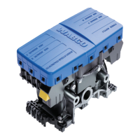
Procedures for removing and installing the ABS relay valve.
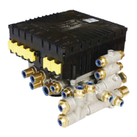
Procedures for removing and installing the ECU/Valve Assembly.
Step-by-step instructions for removing the ECU/Valve Assembly.
Step-by-step instructions for installing the ECU/Valve Assembly.
Specific instructions for tank-mounting the ECU/Valve Assembly.
Instructions for mounting the assembly to a vehicle cross member.
Mounting instructions for 2S/2M and 4S/3M systems to a cross member.
Step-by-step guide for end of line testing using TOOLBOX PLUS™ software.
Procedure for performing a fault code check using blink codes.
Table correlating blink codes with problem areas and actions.
Warnings and cautions for troubleshooting procedures.
Troubleshooting steps for the automatic lift axle system.
Troubleshooting steps for the tag axle system.
Troubleshooting steps for the axle load monitoring system.
Troubleshooting for the tire inflation communication system.
Troubleshooting steps for the door ajar system.
Troubleshooting steps for the integrated speed switch system.
| Brand | WABCO |
|---|---|
| Model | 400 500 320 0 |
| Category | Automobile Accessories |
| Language | English |