Crankcase Rammer Repair
110 wc_tx001548gb.fm
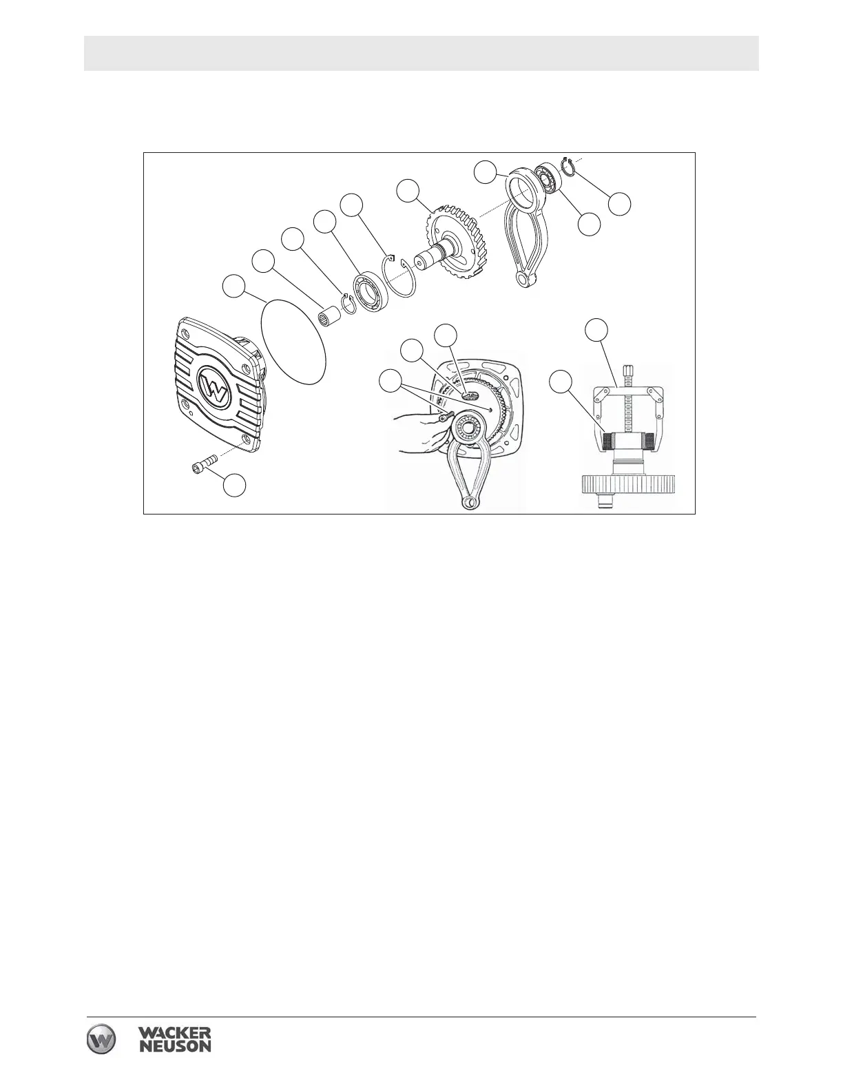
6.1.14 The needle bearing (c) remains intact in the crankcase cover. Inspect
the needle bearing for wear and, if damaged, remove it by using a slide
hammer or similar pulling device.
Assembly
6.1.15 If the needle bearing was removed, press a new bearing into the cover
until the outer race is flush with the flange surface.
6.1.16 Place the large retaining ring over the crank gear shaft.
6.1.17 Press the ball bearing onto the crank gear shaft and reinstall the small
retaining ring.
6.1.18 Press the connecting rod assembly onto the crank gear and secure it
in place with the small retaining ring.
6.1.19 Push the complete crank gear assembly into the bearing housing and
seat the retaining ring in the groove.
6.1.20 Replace the o-ring (b).
6.1.21 Assemble the cover to the crankcase. Torque the screws to 49 Nm (36
ft.lbs.).
6.1.22 Connect the crankcase to the ramming system as follows:
• Position the upper machinery over the guide cylinder.
• Align the connecting rod inside the ram.
• Install the piston pin and the end plugs.
Note: Use new end plugs whenever the piston pin has been removed.
• Fasten the guide cylinder to the crankcase. Apply Loctite 243 and
torque the screws to 43 Nm (32 ft.lbs.).
wc_gr007520
a
b
c
d
e
n
m
f
f
p
f
g
k
j
h
 Loading...