EasyManuals Logo

Wacker Neuson BS 70-2 Repair Manual

Wacker Neuson BS 70-2
156 pages
To Next Page IconTo Next Page
To Previous Page IconTo Previous Page
Page #38 background imageLoading...
Page #38 background image
Engine and Upper Machine Components Repair
38 wc_tx001546gb.fm
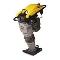
4.6.1 Slide the stop switch (h) into the throttle control bracket and thread the
wiring through the throttle control bracket.
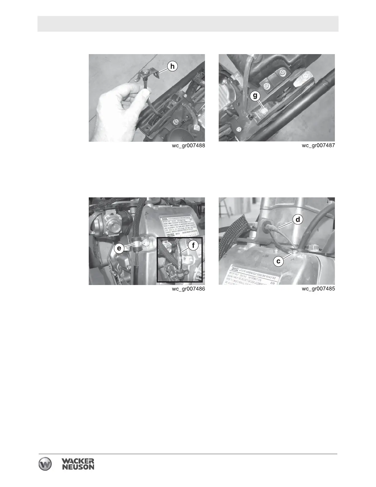
4.6.2 Install the stop switch to the machine with screw
(g). Torque the screw
to 9 Nm (6 ft.lbs.).
4.6.3 Reconnect the wiring connector (f). Apply Loctite 243® to the screw
holding the clamp
(e) and reinstall the clamp (e). Torque the screw to
25 Nm (18 ft.lbs.).
4.6.4 Reconnect the wiring
(c and d) to the engine.
Result
The procedure to replace the stop switch is now complete.

Table of Contents

Other manuals for Wacker Neuson BS 70-2

Questions and Answers:

Question and Answer IconNeed help?

Do you have a question about the Wacker Neuson BS 70-2 and is the answer not in the manual?

Wacker Neuson BS 70-2 Specifications

General IconGeneral
BrandWacker Neuson
ModelBS 70-2
CategoryVibratory rammers & tampers
LanguageEnglish

Related product manuals