Engine and Upper Machine Components Repair
40 wc_tx001546gb.fm
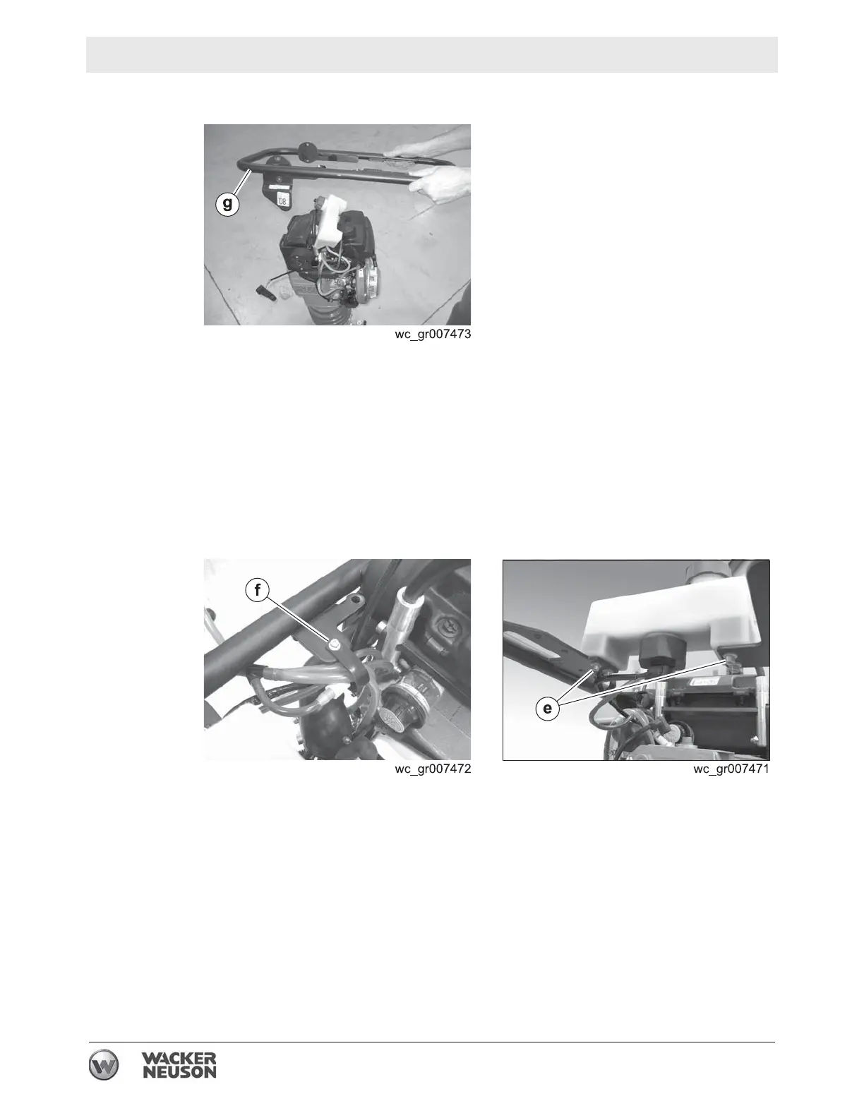
4.7.9 Remove the screws that hold the guide handle (g) to the shock
mounts and remove the guide handle from the machine.
Result
The removal procedure is now complete.
Installation
Perform the procedure below to install the guide handle.
4.7.1 Install the guide handle to the shock mounts. Use Loctite® 243 on the
screws and torque the screws to 24 Nm (18 ft.lbs.).
4.7.2 Feed the hoses through the clips
(f).
4.7.3 Install the oil tank to the guide handle using the screws
(e). Torque the
screws to 9 Nm (6 ft.lbs.).
4.7.4 Thread the upper fuel line (b) through the hole (d) in the guide handle
and connect it to the fuel tank.
 Loading...