4A-2
4A G2.1A/G2.1AE 50 HZ PORTABLE GENERATORS
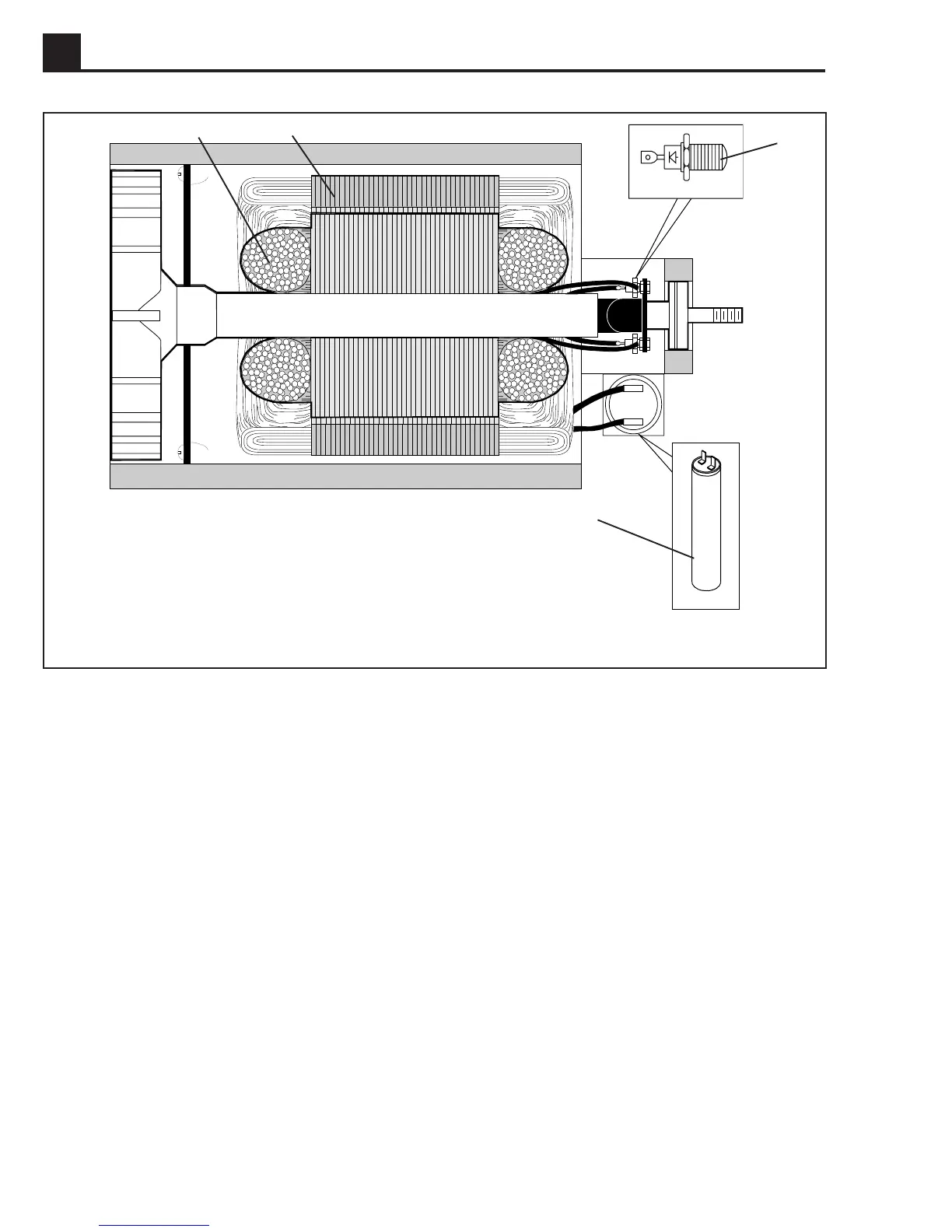
Figure 4-2. Brushless Type Generator
4.2 Rotor (a)
The inside of the rotor shaft is tapered and connected
directly to the taper on the engine crankshaft. This end is
supported by the engine crankshaft bearing. The oppo-
site end of the rotor is supported by a bearing installed in
the generator housing. This end also contains the two
diodes mounted on the diode bracket assembly. There
are two individual coils wound on the rotor. When the
engine is running, these two windings create the mag-
netic field for the main stator windings.
4.3 Stator (b)
The stator houses both the main windings and auxiliary
winding. The main windings are connected directly to the
main circuit breaker to supply power to the output recep-
tacles. The auxiliary winding induces the initial voltage in
the field windings of the rotor and regulates the voltage.
It is connected directly to the main capacitor.
4.4 Capacitor (c)
A capacitor is connected in series with the auxiliary
winding. Its purpose is to regulate the voltage when a
load is applied.
4.5 Diodes (d)
Two diodes are located on the rotor. These diodes form
a half wave rectifier to convert the induced AC voltage in
the rotor windings to DC voltage.
1022SD88
b
a
d
c