5A-10
5A G3.3A/G4.6A/GS4.6A/GS5.7A 50 HZ PORTABLE GENERATORS
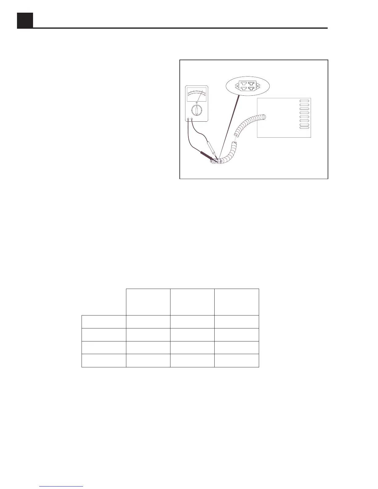
5.14 Stator Windings
The stator includes the two main power windings and the
auxiliary winding. See Figure 5-14.
To check stator windings:
1. Unplug stator connector at control box.
2. Set ohmmeter to lowest scale. Place meter leads on
connector terminals as shown and record resistance
values.
Check resistance values with those listed on Table 5-
1.
A high or low reading indicates an open or shorted
winding and the stator must be replaced.
3. Test for grounded windings by checking for continuity
between winding and metal frame.
If continuity exists, winding is grounded and stator
assembly must be replaced.
Note:
Make sure stator is completely disconnected
from generator. The main windings are intentionally
grounded to the generator to form a neutral and will
give a false reading.
4. Check for continuity between auxiliary winding and
main windings. If continuity exists, the auxiliary winding
has made contact with the main winding and stator
must be replaced.
Table 5-1.
Resistance Values
Resistance values are very small and require a good quality meter with the ability
to be zeroed out. Using a poor quality meter may not provide accurate readings.
All figures are approximate values in ohms.
1024SD05
Figure 5-14. Checking Stator
rotareneG
ledoM
niaM
gnidniW
)noitcesrep(
yrailixuA
gnidniW
rotoR
gnidniW
A3.3G54.090.28.01
A6.4G93.079.13.11
A6.4SG93.079.13.11
V7.5SG27.1
—
3.11