Portable Generator Repair G 2.5A
wc_tx000207gb.fm 31
5.2 Rotor
See Graphic: wc_gr000934
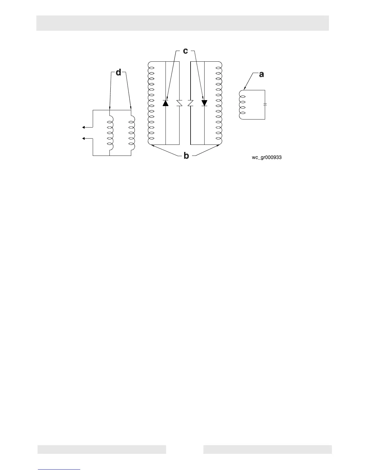
The inside of the rotor shaft (a) is tapered and connected directly to the
taper on the engine crankshaft. This end is supported by the engine
crankshaft bearing. The opposite end of the rotor is supported by a
bearing installed in the generator housing. This end also contains the
two diodes mounted on the diode bracket assembly. There are two
individual coils wound on the rotor. When the engine is running, these
two windings create the magnetic field for the main stator windings.
5.3 Stator
See Graphic: wc_gr000934
The stator (b) houses both the main windings and auxiliary winding.
The main windings are connected directly to the main circuit breaker
to supply power to the output receptacles. The auxiliary winding
induces the initial voltage in the field windings of the rotor and
regulates the voltage. It is connected directly to the main capacitor.