Portable Generator Repair G 3.7A;G/GS 5.6A;GS 8.5V;GS 9.7V
wc_tx000208gb.fm 83
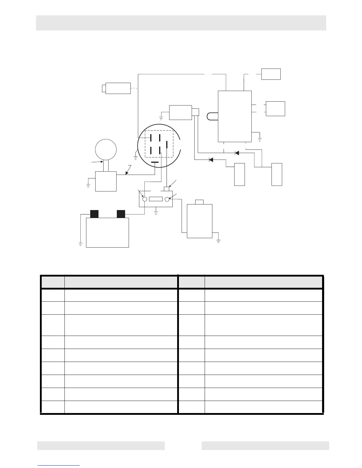
6.35 Vanguard Engine Wiring Schematic (GS 8.5V and GS 9.7V
Models)
Ref. Description Ref. Description
1. Carburetor solenoid 10. Regulator rectifier
2. Stop switch terminal 11. DC output wire
3. 50 Hz. loop
(GS 8.5=yellow, GS 9.7=red)
12. Key switch
4. Module 13. Solenoid
5. Idle down device 14. Battery terminal
6. Actuator 15. Solenoid tab terminal
7. Ignition coils 16. Starter terminal
8. Alternator 17. Battery
9. AC output wires 18. Starter motor
w c _ g r 0 0 0 5 6 8
W
L
G
R
B
G r
1
2
3
4
5
6
7
7
8
1 0
1 2
1 3
1 7
1 8
9
1 1
1 4
1 5
1 6
1
2 3
4
5
6
+