Mobile Generators Factory-Installed Options
wc_tx000380gb.fm 83
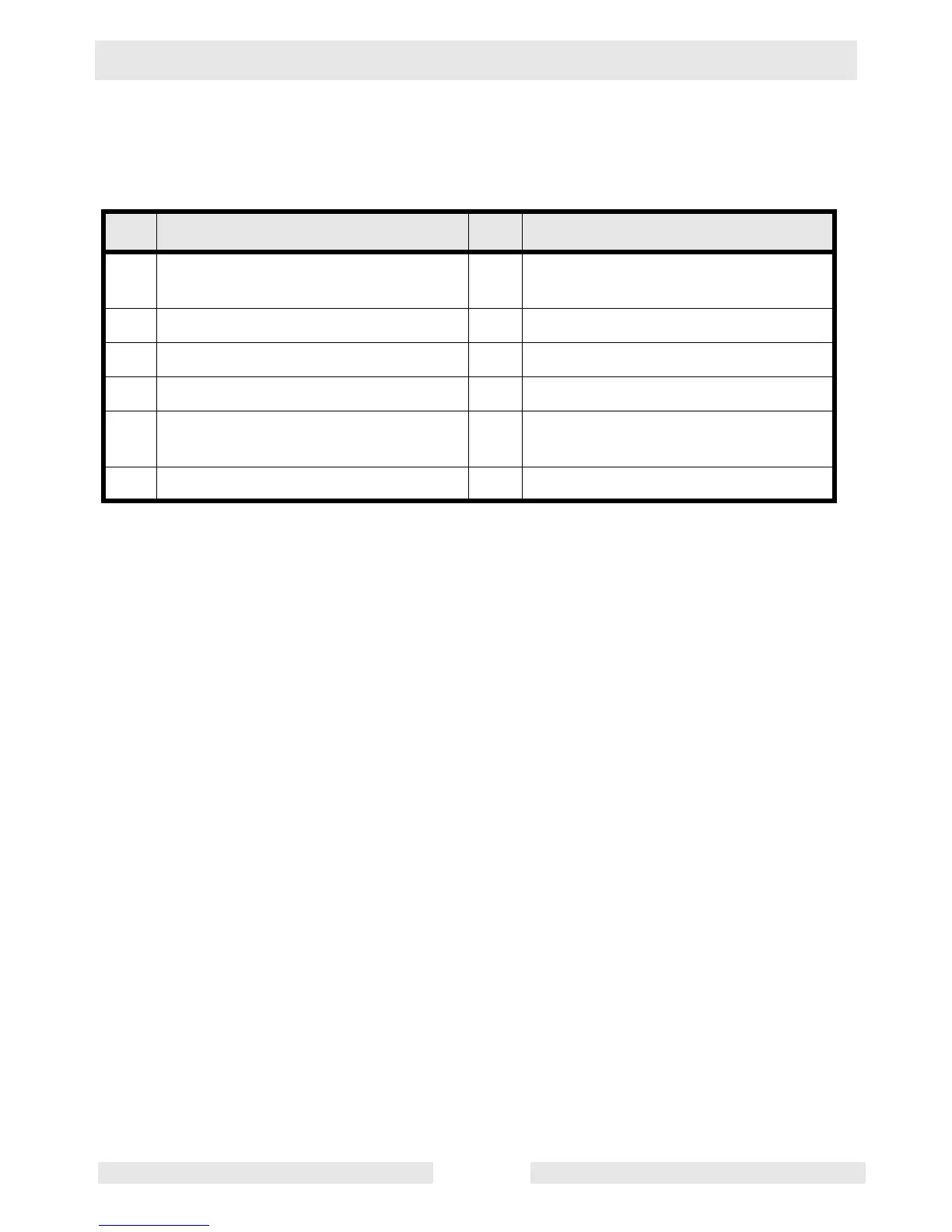
5.10 Wiring Diagram Components
See Graphic: wc_gr001868
Ref Description Ref Description
1 Thermostat module 7 Positive air shutoff solenoid
actuator
2 Terminal block 8 Auxiliary relay terminals
3 1 Amp fuse 9 Plug 1, engine sensor inputs
4 Water level sensor 10 Electronic control board
5 Lube level maintainer low level
switch
11 LCD heater
6 30 Amp circuit breaker 12 Positive air shutoff relay module