Do you have a question about the WAGO 750-8202/040-001 and is the answer not in the manual?
This documentation is only applicable to the "PFC200 2ETH RS TELE XTR" controller and specific firmware versions.
Defines the meaning of various warning and informational symbols used throughout the manual.
Explains the conventions used for decimal, hexadecimal, and binary number representation.
Details the different font types used in the manual and their corresponding meanings.
Covers subject to changes, personnel qualifications, and compliance with underlying provisions.
Outlines conditions for device use, user servicing limitations, and liability exclusions.
Provides essential safety precautions for installing and operating the device.
Details specific conditions and recommendations for using ETHERNET devices.
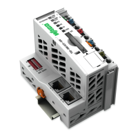
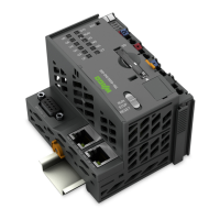
Provides a visual overview of the controller's components and interfaces.
Describes the front and side labeling information on the device.
Details the various connectors on the controller, including data, power, service, and network interfaces.
Explains the function of the LED indicators for power, fieldbus, memory, and network status.
Presents detailed technical specifications for the device, system, supply, clock, programming, and interfaces.
Lists the various certifications and approvals granted to the controller.
Covers network interface configuration, security, configuration, routing, services, and cloud connectivity.
Details operation in switch mode and with separate network interfaces.
Explains user management, passwords, and web protocols for WBM access.
Describes memory card usage, including insertion, removal, formatting, and data backup.
Specifies the approved mounting positions for the WAGO I/O SYSTEM 750 XTR.
Provides guidelines for mounting components onto a carrier rail according to EN 60175.
Details the power jumper contacts and field supply connections.
Explains the system and field power supply requirements, including overcurrent protection.
Covers grounding the DIN rail via framework assembly and insulated assembly.
Provides a checklist of prerequisites before powering on the controller.
Explains how to adapt IP addressing for PC and controller communication.
Details the procedure for changing default WBM and Linux user passwords for security.
Outlines the available methods for configuring the controller.
Step-by-step guide for installing the CODESYS programming software on a PC.
Provides quick start instructions for creating a CODESYS project.
Explains how to configure PLC settings for I/O modules and the controller.
Details the standard memory allocation for program, data, flags, and retain variables.
Explains how to create and use HMI and Web visualizations in CODESYS.
Lists the key features of the Modbus slave implementation in the PFC200.
Describes how to configure Modbus operating modes using CODESYS PLC configuration.
Details WAGO specific registers for system and Modbus information and configuration.
Covers diagnostics for Modbus master, runtime system, and error server.
Describes operating and status messages indicated by controller LEDs.
Explains how diagnostic fault/error messages are displayed using flashing sequences.
Provides an overview of error codes and troubleshooting procedures for I/O LEDs.
Provides instructions for inserting and removing the memory card.
Explains how to perform firmware upgrades and downgrades.
Details the procedure for performing a factory reset, including data overwrites.
Describes the general procedure for removing devices.
Step-by-step guide for removing the fieldbus coupler or controller.
Instructions on how to remove an I/O module from the assembly.
Provides examples of marking configurations according to ATEX, IECEx, NEC, and CEC.
Covers special notes including explosion protection requirements.
Explains the representation of I/O modules in the process image and configuration.
Details the mapping of 2, 8, and 16-channel digital input modules into the input process image.
Describes the mapping of 2, 4, 8, and 16-channel digital output modules into the output process image.
Explains the input process image mapping for 2 and 4-channel analog input modules.
Details the output process image mapping for 2 and 4-channel analog output modules.
Covers serial interfaces, SSI transmitter, distance/angle measurement, counter modules, and CAN gateway.
Lists general CODESYS libraries supported by the controller.
| Brand | WAGO |
|---|---|
| Model | 750-8202/040-001 |
| Category | Controller |
| Language | English |